APPENDIX
A
Manual No. 016-0171-122 Rev. I
213
Appendix A
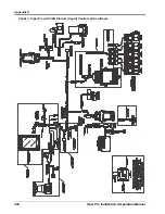
System Diagrams
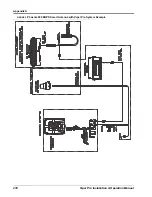
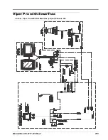
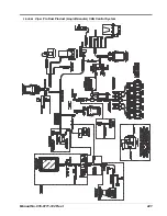
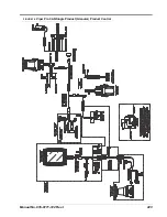
The following diagrams may be helpful for installing or troubleshooting the Viper Pro field computer or product
control system. The following diagrams may show optional features or components not required for operation
and will not apply to all systems if the required hardware has not been installed.
Contact a local Raven dealer for purchasing or more information on components shown in the following
diagrams.
Additional system diagrams are available (free of charge) from the Raven Industries web site:
Note:
Refer to the Generation 2 Cable Connections section on page 19 for an example of a generation 2
cabled system.
Summary of Contents for Viper Pro
Page 1: ... Software Version 3 10 Viper Pro Installation Operation Manual ...
Page 42: ...Chapter 3 32 Viper Pro Installation Operation Manual ...
Page 132: ...Chapter 6 122 Viper Pro Installation Operation Manual ...
Page 138: ...Chapter 7 128 Viper Pro Installation Operation Manual ...
Page 180: ...Manual No 016 0171 122 Rev I 170 Advanced Settings and Features ...
Page 194: ...Chapter 9 184 Viper Pro Installation Operation Manual ...
Page 214: ...Chapter 11 204 Viper Pro Installation Operation Manual ...
Page 262: ...Appendix B 252 Viper Pro Installation Operation Manual ...
Page 276: ...Appendix F 266 Viper Pro Installation Operation Manual ...
Page 284: ...Appendix I 274 Viper Pro Installation Operation Manual ...
Page 292: ...Appendix J 282 Viper Pro Installation Operation Manual ...
Page 299: ......

