Appendix B
236
Viper Pro Installation & Operation Manual
PWM Control Valve Tuning
The Viper Pro field computer provides three methods for fine tuning a PWM or PWM close valve used for
controlling product application:
PWM Manual Calibration
The operator may enter the known values for the following PWM valve calibration settings within the Product
Control Settings area:
Note:
The PWM valve will not be operated during manual calibration. It is recommended to verify that
any changes to these settings will have the desired affect before controlling product application.
Refer to the Node Control Settings Screen (Page 2) section on page 140 for more information on
the min pw, max pw values and the Node Control Settings Screen (Page 3) section on page 141
for details on the standby pressure, preset pw and pw freq values.
PWM Calibration Assistance
The calibration assistant allows the operator to manually increase or decrease the PWM output using on-
screen controls and set the PWM minimum, maximum, frequency and preset values based upon observed
operation.
Note:
It is recommended to perform the calibration process with water in liquid tanks or while performing
a catch test with a dry or granular application system.
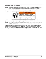
To use the calibration assistant mode, toggle the vehicle master switch and at least one section to the on
position. To stop the PWM output at any time during the calibration process, toggle the vehicle master switch to
the off position.
Note:
Refer to the Node Control Settings Screen (Page 2) section on page 140 for more information on
the min pw, max pw values and the Node Control Settings Screen (Page 3) section on page 141
for details on the standby pressure, preset pw and pw freq values configured using the calibration
assistant.
1.
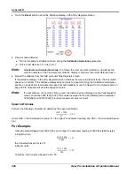
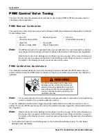
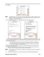
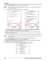
Touch within the Product Control Settings area on the CAN Controller Status screen. The first Node 1
Settings screen will display.
•
Min PW
(Minimum Pulse Width)
•
Standby Pressure
•
PW Freq
(Pulse Width Frequency)
•
(Max PW)
Maximum Pulse Width
•
Pre Set PW
(Preset Pulse Width)
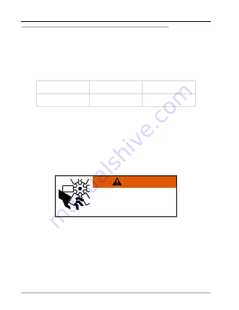
WARNING
The PWM valve output will increase and
decrease as the up and down arrows are
selected. Keep any bystanders away from
areas where product may be expelled and
moving components when performing the
calibration process.
Summary of Contents for Viper Pro
Page 1: ... Software Version 3 10 Viper Pro Installation Operation Manual ...
Page 42: ...Chapter 3 32 Viper Pro Installation Operation Manual ...
Page 132: ...Chapter 6 122 Viper Pro Installation Operation Manual ...
Page 138: ...Chapter 7 128 Viper Pro Installation Operation Manual ...
Page 180: ...Manual No 016 0171 122 Rev I 170 Advanced Settings and Features ...
Page 194: ...Chapter 9 184 Viper Pro Installation Operation Manual ...
Page 214: ...Chapter 11 204 Viper Pro Installation Operation Manual ...
Page 262: ...Appendix B 252 Viper Pro Installation Operation Manual ...
Page 276: ...Appendix F 266 Viper Pro Installation Operation Manual ...
Page 284: ...Appendix I 274 Viper Pro Installation Operation Manual ...
Page 292: ...Appendix J 282 Viper Pro Installation Operation Manual ...
Page 299: ......


