Appendix C
254
Viper Pro Installation & Operation Manual
Testing the Speed Sensor Cable
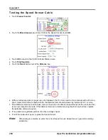
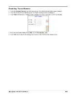
1.
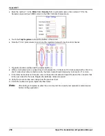
Touch
Product Control
.
2.
Touch the
Miscellaneous
box. Enter 1000 as the Speed Cal and touch
OK
.
3.
Touch
OK
to return to the CAN Controller Status screen.
4.
Touch
Tally Registers
.
5.
Touch the
Reset
button next to the
Distance
box.
6.
With a small jumper wire (or paper clip), short between the 10 o’clock and 6 o’clock sockets with a ‘short-no-
short’ motion. Each time contact is made, the Distance total should increase by increments of 1 or more.
7.
If the Distance total does not increase, remove the section of cable and repeat the test at the connector that
is the next closest to the node. If the distance total now increments during the short-no-short test, replace
the defective cable as required.
8.
If no pulses are registered, perform the above voltage checks.
9.
If all of the cables test ‘good’, replace the Speed Sensor.
Note:
After testing is complete, re-enter the correct Speed Cal and Speed Sensor type before starting
application.
Summary of Contents for Viper Pro
Page 1: ... Software Version 3 10 Viper Pro Installation Operation Manual ...
Page 42: ...Chapter 3 32 Viper Pro Installation Operation Manual ...
Page 132: ...Chapter 6 122 Viper Pro Installation Operation Manual ...
Page 138: ...Chapter 7 128 Viper Pro Installation Operation Manual ...
Page 180: ...Manual No 016 0171 122 Rev I 170 Advanced Settings and Features ...
Page 194: ...Chapter 9 184 Viper Pro Installation Operation Manual ...
Page 214: ...Chapter 11 204 Viper Pro Installation Operation Manual ...
Page 262: ...Appendix B 252 Viper Pro Installation Operation Manual ...
Page 276: ...Appendix F 266 Viper Pro Installation Operation Manual ...
Page 284: ...Appendix I 274 Viper Pro Installation Operation Manual ...
Page 292: ...Appendix J 282 Viper Pro Installation Operation Manual ...
Page 299: ......

