Appendix C
256
Viper Pro Installation & Operation Manual
4.
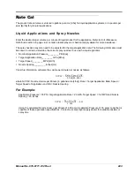
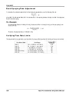
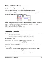
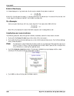
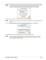
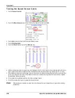
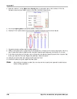
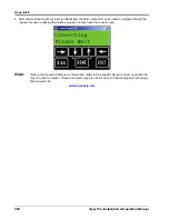
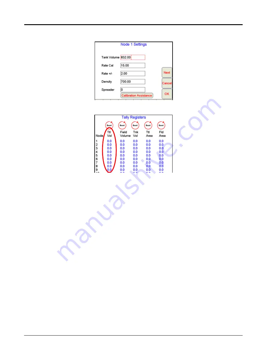
Enter the number ‘1’ in the
Meter Cal
or
Density
field. In granular modes, enter a value of ‘0’ for the
Spreader value and touch
OK
to return to the CAN Controller Status screen.
5.
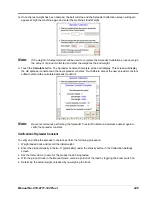
Touch the
Tally Registers
button at the bottom of the screen.
6.
Note the ‘Ttl Vol’ (total volume) column and the registered values for each control channel.
7.
Toggle the section switches and the master switch on.
8.
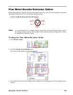
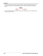
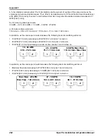
With a small jumper wire (or paper clip), short between the 2 o’clock and 6 o’clock sockets with a ‘short-no-
short’ motion. Each time contact is made, the total volume should increase by increments of 1 or more.
9.
If the total volume does not increase, remove the section of cable and repeat the test at the connector that
is the next closest to the node. Replace the defective cable as required.
10.
Verify the pin connection and voltage from the previous chart.
11.
If all of the cables test ‘good, replace the flow meter.
Note:
After testing is complete, re-enter the correct meter cal or density and spreader constant values
before starting application.
Summary of Contents for Viper Pro
Page 1: ... Software Version 3 10 Viper Pro Installation Operation Manual ...
Page 42: ...Chapter 3 32 Viper Pro Installation Operation Manual ...
Page 132: ...Chapter 6 122 Viper Pro Installation Operation Manual ...
Page 138: ...Chapter 7 128 Viper Pro Installation Operation Manual ...
Page 180: ...Manual No 016 0171 122 Rev I 170 Advanced Settings and Features ...
Page 194: ...Chapter 9 184 Viper Pro Installation Operation Manual ...
Page 214: ...Chapter 11 204 Viper Pro Installation Operation Manual ...
Page 262: ...Appendix B 252 Viper Pro Installation Operation Manual ...
Page 276: ...Appendix F 266 Viper Pro Installation Operation Manual ...
Page 284: ...Appendix I 274 Viper Pro Installation Operation Manual ...
Page 292: ...Appendix J 282 Viper Pro Installation Operation Manual ...
Page 299: ......


