background image

Chapter 4

36

Viper Pro Installation & Operation Manual

3.

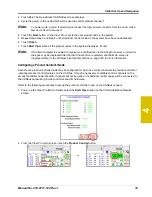
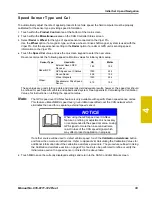
Select one of control channels currently assigned to the product controller node and touch within the 

Product Control Settings 

area.

4.

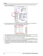
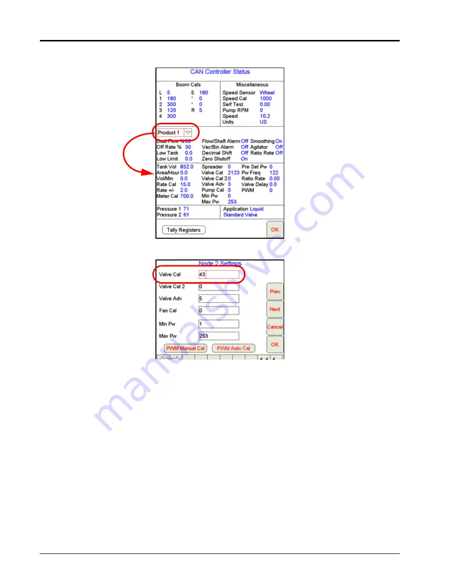
The first node settings screen for the selected control channel will be displayed. Touch the 

Next 

button 

along the right side of the screen to display the second node settings screen.

5.

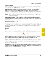
Touch the displayed valve cal value. Using the on-screen keyboard, enter a valve cal value of ‘900#’ where 
# is the desired number of control channels assigned to the product controller node.
For example, enter a value of ‘9005’ in the valve cal to enable all five control channels on the air cart node.

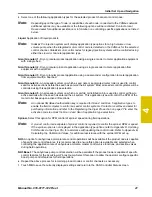
6.

Touch the 

OK 

button until the Viper Pro main screen is displayed.

7.

Select the 

Menu 

button in the lower, right corner of the display and select the 

Exit

Exit to Menu 

options.

8.

When the Program Selection Menu screen displays, select the 

Sprayer/Spreader 

option to restart the Viper 

Pro application. The CAN Initialization Results screen will display again.

9.

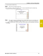
Verify that the appropriate control channels are displayed before touching the 

Start Viper 

button. Review 

the 

Configuring a Product Controller Node

 section on page 35 to disable control channels on the product 

controller node.

Summary of Contents for Viper Pro

Page 1: ... Software Version 3 10 Viper Pro Installation Operation Manual ...

Page 2: ... repairs made outside our facilities nor damages resulting from inadequate maintenance of this system As with all wireless and satellite signals several factors may affect the availability and accuracy of wireless and satellite navigation and correction services e g GPS GNSS SBAS etc Therefore Raven Industries cannot guarantee the accuracy integrity continuity or availability of these services and...

Page 3: ...AgX Compatibility 5 Optional Features 5 The Viper Pro Interface 6 Active Matrix Transflective Touch Screen 6 Front Panel 7 File Transfer 8 Rear Panel 9 Viper Pro Care and Use 10 Technical Specifications 10 Updates 12 Chapter 3 Installation Start Up and Registration 13 Overview of the Installation Process 13 Kit Contents 14 Mounting the Field Computer 15 Cable Platforms and Connections 16 Generatio...

Page 4: ...wering Down the Viper Pro 51 Navigating the Viper Pro Interface 53 Main and Job Screen Displays 53 Controller Status Screen 62 Chapter 5 Using the Viper Pro System 65 Overview of Job Files and Features 65 Overview of Job Types 66 Overview of Job Features 66 Starting a New AgX Job 69 Assign or Create a Product Chain Profile 72 Selecting Control Channels 74 Booms 75 Default Rate 75 Conversion Factor...

Page 5: ...ng Alarm Conditions 102 Creating Application Reports 103 To Enter Report Information 104 Chapter 6 Viper Pro Guidance 109 Guidance Views 109 Swath Guidance Patterns 110 Setting the Straight A B Line Pattern 110 Set A B Line by Heading 112 Setting the Fixed Contour Pattern 113 Setting the Last Pass Pattern 113 Setting the Pivot Pattern 114 Using the Guide Tab 115 Screen Icons 117 A B Lines 118 Savi...

Page 6: ...creens 145 AutoBoom Status Indicator 146 Wireless Communication Status 146 Menu 147 Exit Button 147 About Button 147 Web Button 149 Setup Button 150 File Maintenance 150 Start Job 151 Setup Menus 151 Registration Keys 151 Maps 152 Street Maps 152 Scout Maps 154 Coverage Maps 155 Prescription Rx Maps 157 Local Settings 162 Power Option 162 Serial Communication Port Setup 163 GPS Comm Port Setup 163...

Page 7: ...ter 10 Using AutoBoom 185 AutoBoom Status Display 186 Chapter 11 File Maintenance and Editing Reports 187 Overview 187 File Maintenance 187 Preparing a USB Flash Drive for File Maintenance 188 Flash Drive File Structure 190 RDE Folder 190 Viper Folder 190 Performing File Maintenance 192 Wireless File Transfer 193 Uploading Prescription Maps from a USB Flash Drive 194 USB File Transfer and Advanced...

Page 8: ... 210 Variable Rate Control VRC Error Messages 210 GPS Error Messages 211 CAN Troubleshooting 212 APPENDICES Appendix A System Diagrams 213 Appendix B Calculating the Calibration Values 225 Appendix C Testing Extension Cables 253 Appendix D Updating CAN Nodes via the Viper Pro 257 Appendix E Using the Front Panel Program with the Viper Pro System 261 Appendix F Tiered Booms 263 Appendix G Load Cell...

Page 9: ...aces provided Write down the calculated calibration values in the spaces provided Units US Acres SI Hectares Turf 1000 Square Feet Speed Sensor SP1 Wheel Speed SP2 Radar Speed Cal Control Channel 1 Control Channel 2 Control Channel 3 Control Channel 4 Control Channel 5 Control Type Valve Type Control Channel 6 Control Channel 7 Control Channel 8 Control Channel 9 Control Channel 10 Control Type Va...

Page 10: ...et US Volume per Acre PPM Pounds per Minute SI Volume per Hectare kg min Kilograms per Minute TU Turf Units Volume per 1 000 Square Feet PPA Pounds per Acre Metric Values kg ha Kilograms per Hectare Turf Unit Values Fluid Ounces Conversion Formula Liters Conversion Formula Pounds Conversion Formula Original METER CAL Number 128 Original METER CAL Number 3 785 Original METER CAL Number Weight of On...

Page 11: ... Be alert and aware of surroundings Do not operate the field computer while under the influence of alcohol or an illegal substance Remain in the operator s position in the machine at all times when the field computer is engaged in product control or feature operation The machine operator is responsible for disabling or turning off automatic control features before leaving the operator s position D...

Page 12: ...roved maintenance instructions When installing hydraulics or performing diagnostics maintenance or routine service ensure that precautions are taken to prevent any foreign material or contaminants from being introduced into the machine s hydraulic system Objects or materials that are able to bypass the machine s hydraulic filtration system will reduce performance and possibly damage the hydraulic ...

Page 13: ...nagement system Viper Pro is a multi purpose precision tool offering the latest technology in precision agriculture with features including product application control field mapping and application reports as well as in field guidance via a connected DGPS Differential Global Positioning System receiver FIGURE 1 Raven Viper Pro Field Computer ...

Page 14: ...ed data or scouting information This as applied information can be used to compare the field prescription to the actual application and provide valuable documentation of the application The Viper Pro system will store the application report and datalogged information on the field computer until transferred to a USB flash drive or uploaded to the Slingshot web site for creating or printing applicat...

Page 15: ...eld computer Viper Pro software version 3 4 or higher is required to utilize the AgX features with the field computer An AgX activation key is required to use AgX recommendations on the Viper Pro field computer Application of multiple products using the AgX feature will require a multiple product VRA key Optional Features In addition to the product application control capabilities of the field com...

Page 16: ...atrix Transflective Touch Screen Active Matrix Transflective touch screen technology offers clear visibility across a range of lighting conditions and even in direct sunlight while the touch screen functionality places menus and options literally at the operator s finger tips CAUTION Do not use sharp objects such as ball point pens pocket knives screwdrivers etc on the Viper Pro display ...

Page 17: ... this port to transfer compatible Viper Pro files Note The USB flash drive must be set up with the Viper Pro file structure See Chapter 11 File Maintenance and Editing Reports for setting up the required file structure on the USB flash drive NOTICE Failure to close a job before turning the field computer power off may result in a loss of information for that job Make sure to properly close any ope...

Page 18: ...and 4 GB of storage and should be used to manually transfer files to and from the field computer USB flash drives may be purchased directly from Raven Industries 4 GB USB Flash Drive P N 524 0002 065 as well as many retail locations FIGURE 3 USB Flash Drive Note Install the USB flash drive only when transferring files Do not start the Viper Pro or leave the USB flash drive in the Viper Pro during ...

Page 19: ...e also located on the back of the Viper Pro The field computer part and serial numbers and revision letter are printed on the tag located on the back of the field computer Please have this information available when contacting customer support CAUTION Damage to the field computer may occur if the USB ports are used to charge mobile devices such as cellular phones tablets or mp3 devices The USB por...

Page 20: ...oute cables to avoid tripping hazards and to keep the wires from pinching or breaking When temperatures are expected to be 32 F 0 C or lower remove the field computer from the vehicle and store it in a climate controlled environment Damage to the field computer may occur if the USB ports are used to charge mobile devices such as cellular phones tablets or mp3 devices The USB ports should only be u...

Page 21: ... CAN Lo 4 CAN Lo 5 DGPS Receive 5 Auxiliary DCD 6 DGPS Transmit 6 Not Used 7 DGPS CTS 7 Auxiliary Receive 8 DGPS RTS 8 Auxiliary Transmit 9 Console Transmit 9 Auxiliary CTS 10 Console Receive 10 DTR 11 RS232 Ground 11 Auxiliary RTS 12 Console CTS 12 RS232 Ground 13 Console RTS 13 Not Used 14 12 V Ignition 14 Radar Out 15 12 V Switched 16 Battery Positive Auxiliary Amp Connection Main Amp Connectio...

Page 22: ...ntation and the overall service we provide We appreciate the opportunity to see ourselves as our customers see us and are eager to gather ideas on how we have been helping or how we can do better To serve you best please send an email with the following information to techwriting ravenind com Viper Pro Installation Operation Manual Manual No 016 0171 122 Rev I Any comments or feedback include chap...

Page 23: ...or instructions on installing additional hardware with the Viper Pro refer to instructions provided with the additional or optional component s Refer to the Raven CANbus Network Installation Manual for additional information on building a CAN Controller Area Network system Basic installation of the Viper Pro system is as follows 1 Review kit contents 2 Mounting the Viper Pro field computer 3 Mount...

Page 24: ... 016 0171 147 Bracket Mounting 107 0171 415 Cable Chassis Interface 115 0172 001 Part Description Part Number Console Viper Pro 063 0172 879 Clamp Mounting 106 0159 607 Bracket Mounting 107 0171 415 Knob Mounting Clamp 309 1000 021 Cable Main Interface 115 0171 746 Manual Viper Pro 016 0171 122 Quick Reference Guide Viper Pro 016 0171 147 Other Available Components Part Number Cable Auxiliary Inte...

Page 25: ...on where it will not be jarred during normal equipment operation Keep the field computer clear of moving elements within the machine s cab Keep cable routing in mind when selecting a mounting location to avoid tripping hazards or damage to the cable during normal operation To mount the field computer Note If the CAN Switch Box will be installed with the Viper Pro field computer use the mounting ha...

Page 26: ...NOTICE Please review the Raven CANbus Network Installation Manual for installation instructions for the specific cable platform being installed with the field computer prior to beginning installation Contact a local Raven dealer for assistance or to purchase additional components necessary to set up the CANbus system CAUTION Viper Pro field computers with hardware revision A or higher should be co...

Page 27: ... as a clean power bus bar or junction box 2 Connect the red lead wire to a clean 12V DC power source CAUTION Even when the field computer is powered off the computer will draw a small current from the battery Connect the red wire to a controlled power source or if the machine will not be in use for an extended period of time remove power from the field computer To prevent accidental data loss the ...

Page 28: ...ower out of the field computer When the field computer is powered 12V DC is applied to the orange wire to power an external device If more than 1 amp is required to power a device connected to the orange wire install a relay to switch the higher currents FIGURE 3 Relay P N 415 1001 009 Terminals To 12V Switched Orange Wire Key Switch 12V Switched to Node Power Batt Batt ...

Page 29: ...stration Generation 2 Cable Connections The chassis cable platform requires the following components Machine specific chassis cable Viper Pro chassis interface cable P N 115 0172 001 CAN Switch Box kit P N 117 5020 002 FIGURE 4 Generation 2 Cable Connection Diagram ...

Page 30: ...nvizio Pro Viper Pro chassis interface cable P N 115 0172 001 2 Insert this connector into the To Cab Cable on the chassis cable previously installed on the vehicle Thread the connectors together to secure the connection 3 Route the end of the cable with two round connectors to the back of the Viper Pro and connect to the main and auxiliary ports 4 Connect the 2 pin Deutsch connector labeled Switc...

Page 31: ...from the connected DGPS Receiver refer to the Serial Communication Port Setup section on page 163 Note The Internal GPS Receiver Output connector on the chassis interface cable is not used with the Viper Pro field computer FIGURE 5 DGPS Receiver Connection Example Viper Pro with Phoenix 200 Integrated Receiver Antenna NOTICE Carefully read and follow all installation instructions included with the...

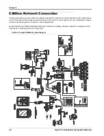
Page 32: ...system at any time Ten product control nodes can be connected to the Viper Pro control system for any combination of liquid granular chemical injection or spinner control applications Review the Raven CANbus Installation Manual for details on building a CANbus network or adding a control channel to an existing product control system FIGURE 6 Sample CANbus System Diagram ...

Page 33: ...lled properly as instructed in the previous sections Once installation of the Viper Pro precision application management system has been completed and verified the field computer may be powered up To start up the Viper Pro 1 Press the power button on the Viper Pro The field computer will take approximately 2 minutes to power up Note Pressing the power button when the following prompt is displayed ...

Page 34: ...de Refer to the Raven OmniSeed Installation and Operation Manual for more information on operation of the field computer in this mode Brightness Control option to adjust the screen brightness Front Panel option to configure Raven DGPS Receivers directly with the Viper Pro using the Front Panel Program See Appendix E Using the Front Panel Program with the Viper Pro System for detailed instructions ...

Page 35: ...to Detecting CANbus Nodes section on page 33 for more information on the CAN Initialization Results screen or information on setting up or troubleshooting the CANbus or CAN nodes If the field computer is enabled to receive web notifications via the Slingshot server a prompt or dialogue may be displayed after the Start Viper button is selected and the Main screen is displayed Refer to the Wireless ...

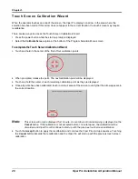
Page 36: ...tion points 2 When prompted release the point The next calibration point will be displayed 3 Touch and hold the center of each remaining calibration point as they are displayed 4 Once all points have been calibrated touch in various areas of the screen to verify that the arrow appears in the correct location Note This screen will only be displayed for 1 minute A count down of time remaining is dis...

Page 37: ...re allows the Viper Pro to automatically control product rates in reference to a prescription map or maps Weather Module The Viper Pro is capable of reading information from an external weather station and recording this information into the application report Refer to Creating Application Reports section on page 103 or Appendix I Weather Station or contact a local Raven dealer for more informatio...

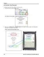
Page 38: ...register your product 3M8828 000102 03667 0102 000L To register your product and receive an Activation Key go to www ravenprecision com select the Support tab and choose Product Registration Product Options Multi Product 077 0171 152 Weather Station 077 0180 030 Order Number XXXXXX PO Number XXXXXX ______________________________________________________________________________ The Viper machine id ...

Page 39: ... module have not been purchased the registration code sheet will not be supplied Write down the machine ID and validation code from the Viper Pro system on a blank piece of paper for future use 3 Touch the Next button The Key 1 screen displays This is the screen on which the activation key code will be entered Do not navigate away from this screen 4 On a home or office computer go to the Raven App...

Page 40: ...n displays 6 Fill in the machine ID validation code and registration code from the registration code sheet Click the Next button 7 Fill in the requested information and then click Next 8 If the registration was processed successfully prompt similar to the following will be displayed ...

Page 41: ...the on screen keyboard to enter the activation key received from the Raven web site see step 8 Note If the Viper Pro has been registered previously touch the Menu button on the main screen and select Setup then Reg Keys and Next to display the Key 1 screen to enter an activation key 11 Press OK The activation key is saved to the Viper Pro field computer and the appropriate activation keys are vali...

Page 42: ...Chapter 3 32 Viper Pro Installation Operation Manual ...

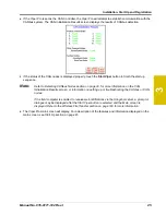
Page 43: ...d node and all product nodes connected to the CANbus Note If the Viper Pro establishes communication with a node it displays as Found on the CAN Initialization Results screen Nodes not detected during startup will not be displayed on this screen If a product node is not found by the Viper Pro field computer troubleshoot the system to determine why Viper cannot communicate with the node See Chapter...

Page 44: ...de logic power and grounds connected to a dirty power source dirty power is defined as any circuit with a variable load that exceeds 1 ampere This is especially true of circuits loaded by electrical coils 3 Field computer and nodes connected to different power and or ground sources e g battery alternator or power bus This can result in components operating at different voltage planes Connect the f...

Page 45: ...r a prompt or dialogue may be displayed after the Start Viper button is selected and the Main screen is displayed Refer to the Wireless File Transfer section on page 193 for more information Configuring a Product Controller Node Each Raven product controller node may be configured for up to five control channels to provide controls for individual product control features on the CANbus It may be ne...

Page 46: ...gned to the product controller node For example enter a value of 9005 in the valve cal to enable all five control channels on the air cart node 6 Touch the OK button until the Viper Pro main screen is displayed 7 Select the Menu button in the lower right corner of the display and select the Exit Exit to Menu options 8 When the Program Selection Menu screen displays select the Sprayer Spreader opti...

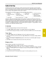
Page 47: ...ect the language displayed on the Viper Pro field computer 1 Touch Menu Setup Local and Lang The Language Setup screen will be displayed 2 Touch the desired language for display on the field computer and select OK to return to the main screen Time Zone 1 Touch Menu Setup Local and Time Zone The Time Zone Setup screen displays 2 Touch the desired time zone from the list Use the Up or Down arrows if...

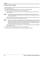
Page 48: ...iper Pro will be connected to a separate Raven rate control console via a serial cable select the specific rate controller from the list of controller model options Note In this mode the calibration information presented in following sections will need to be entered on the serial control console To complete the initial set up of the Viper Pro field computer refer to the Boom or Section Cal section...

Page 49: ...uctions on refining the speed cal value Note The GPS speed over CANbus feature is only available with specific Raven speed sense nodes This feature utilizes NMEA speed over ground data transmitted over the CAN network which eliminates the need for a separate external speed sensor If another source will be used to detect vehicle speed touch the Calibration Assistance button and follow the on screen...

Page 50: ...iquid applications The valve stops adjusting rate and remains at the current position when the control signal is removed This valve type setting is also used when controlling a CAN Motor Control node Fast Same as the Standard valve but can change setting at a higher rate Fast Close Same as the Standard valve but can change setting at a higher rate and closes completely when the master switch is in...

Page 51: ...ow to active sections after the seed has entered the air system This application type will control the RPM of the meter roller based upon active drill sections Note An optional OmniSeed authorization key is required for Gran 4 and Gran 5 application types to enable the field computer to control air seeder control systems Contact a local Raven dealer for purchasing information and refer to the Regi...

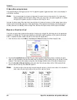
Page 52: ...eter Cal s section to continue with the initial set up process Meter Cal s Note The meter cal is required when the corresponding product node or control channel will be controlling application of a liquid product The meter cal value is typically found on the flow meter If the product node or control channel is set to control application of a dry or granular product refer to the Spreader Constant a...

Page 53: ...increments the formula to calculate the spreader constant is Where SC the Spreader Constant L Length of belt travel in centimeters per 1 revolution of the encoder GH Gate Height in centimeters and GW Gate Width in centimeters To enter the calculated Spreader Constant 1 Touch within the Product Control area at the bottom of the main screen 2 Make sure that Node 1 is selected on the CAN Controller S...

Page 54: ...lues will be replaced by the flow cal and pr Sgain pressure system gain values See the Node Feature Settings Screen Page 2 section on page 136 for information on enabling the dual loop control feature Refer to the Dual Loop Control Cals section on page 45 for more information on setting the flow cal and pr Sgain values 1 Touch within the Product Control area at the bottom of the main screen 2 Make...

Page 55: ...he valve cal and valve cal 2 values if the dual loop control feature is enabled See the Dual Loop Control section on page 137 for details on the dual loop control mode Refer to the Node Feature Settings Screen Page 2 section on page 136 for information on enabling the dual loop control feature Flow Cal Note It is recommended to set the Sgain value prior to making any adjustments to the flow cal va...

Page 56: ...nt or implement This procedure sets the overall width used for guidance of the machine as well as boom or implement section widths used for control of product application 1 From the main screen touch Menu then Setup and Boom to display the Boom Setup screen 2 Touch the Overall Width field and use the on screen keypad to enter the machine or implement swath width The overall width is the machine wi...

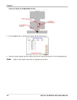
Page 57: ...S or centimeters Metric 3 If the boom or implement is behind the GPS antenna enter a negative value for the fore aft offset FIGURE 1 Example of the Fore Aft Measurement Left or Right Offset The left right offset is the distance from the GPS antenna to the center line of the boom or implement Note The left right offset must be measured parallel to the boom or implement width See Figure 2 below To s...

Page 58: ... Touch the Next button to continue to the Boom Section Setup screen 5 Use the on screen keypad enter the width of each boom or implement section in the corresponding field Note Enter a section width value of zero for skipped boom sections DGPS Antenna Center of Boom Implement Left Right Measurement ...

Page 59: ...ion location settings This screen displays an overview of the section configuration at the top of the screen the current values for the overall boom system width and offsets and the width and offset from the GPS antenna for each section 7 For simple boom configurations check that the system overview reflects the actual physical application equipment or implement and touch OK to save the displayed ...

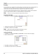
Page 60: ...mputer for the specific application and equipment type Note Profiles do not store any information contained in the CAN nodes Saving Profile Information 1 Select Menu then Setup Local Profile and Save Profile The Save Profile screen opens 2 Using the screen keyboard enter a name for the profile 3 Press OK A confirmation screen displays Note Before saving a profile make sure that all settings are co...

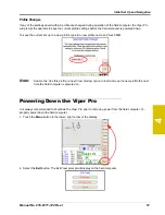
Page 61: ...t up in a new profile type in a new profile name and touch OK Note Enable the Use this profile on next Viper startup option to load and use the new profile the next time the field computer is powered on Powering Down the Viper Pro It is always recommended to shutdown the Viper Pro prior to removing power from the field computer To properly power down the field computer 1 Touch the Menu button in t...

Page 62: ... is in progress when the exit button is selected the Viper Pro will display a warning alerting the operator Raven recommends closing any open jobs before exiting the Viper Pro application to avoid losing job information CAUTION Pressing and holding the Power button to shutdown the Viper Pro may result in a loss of field application data and is not recommended Holding the power button to shut off t...

Page 63: ...the Main tab Before starting a job be sure that the correct profile is selected During an active job the map area displays coverage or as applied information based upon the product node or control channel selected in this area Note The Viper Pro may also display an on screen light bar at the top of the screen during an active job Refer to the Light Bar Guidance section on page 168 to enable the on...

Page 64: ... displayed on the Viper Pro is for reference only and is not used to adjust product rate Verify that the speed reading on the serial controller is accurate Review the Speed Sensor Type and Cal section on page 39 if the speed reported by the Viper Pro does not approximate the actual vehicle speed Dual Pressure Displays Note Pressure readings are displayed for operator display only and do not affect...

Page 65: ...tact a local Raven dealer Main Tab The Main tab is only available when the field computer is not providing guidance or logging application or field data in an active job The Main tab displays the current vehicle location with respect to previously saved field boundaries or on a street map if available to help navigate between fields Note Refer to the Street Maps section on page 152 for assistance ...

Page 66: ...rea information is no longer associated with the boundary The Prescription Rx tool is available on the Rx and Cov tabs if a prescription map has been loaded for the job in progress The Prescription Rx tool may be used to view rate zone or applied coverage information To use the Prescription Rx tool 1 Touch the Prescription Rx icon until a red box displays on the icon 2 Touch the map area The field...

Page 67: ...information cannot be modified from this view To modify the data displayed refer to the Tally Registers section on page 98 See Appendix I Weather Station for information on displaying weather data in this area using the optional weather station Information for any active alarm conditions is also displayed in this area If an alarm condition is detected the Display Data icon will change to a red ala...

Page 68: ... display character for each section displays green if the section is on or active If a section is toggled off the status indicator for the corresponding section will display gray Note If an optional AccuBoom automatic boom section control system is installed with the Viper Pro sections currently controlled by the AccuBoom feature will display with a blue background Touch within the Booms area acce...

Page 69: ... GPS Status screen Refer to the GPS Status Screens section on page 144 for details on using the GPS Status screen When connected to a compatible GPS receiver the Viper Pro will display the source of GPS corrections currently received An audible tone will sound anytime the correction source changes The Viper Pro will display the following on the Main screen SBAS This mode displays with any Satellit...

Page 70: ... to a Raven CANbus system Note See the Controller Status Screen section on page 62 for an overview of the settings and information areas displayed on the CAN Controller Status screen Refer to Review Chapter 8 Advanced Settings and Features for more information on the Product Control status and using the CAN Controller Status screens on the Viper Pro field computer SmarTrax Status Area and Steering...

Page 71: ...Refer to Menu section on page 147 for details on the settings features and options accessible through the main screen menu button Exit or Restart the Viper Pro application or shutdown the field computer View field computer software and hardware version information Access the internet if a wireless access device is connected and properly configured Setup the following control and feature items Regi...

Page 72: ...een displays information from the product rate controller or a CANbus control system Controller Status When connected to a separate product rate control console the Viper Pro Controller Status screen displays boom section and product rate information provided by the rate controller The following is an example of the Controller Status screen with the Viper Pro configured to interface with a Raven S...

Page 73: ...t node or control channel before changing any settings The Feature Settings Area displays an overview of the currently programmed alarm settings and features for the selected product node or control channel Refer to the Feature Settings Area section on page 134 for more information on available features accessible through the feature settings area The Product Control Settings Area displays the cur...

Page 74: ... or channel or the Viper Pro odometer Note The tally registers information may also be displayed by selecting the Display Data icon on the main screen The Current Alarms button is displayed only when an alarm condition is detected by the Viper Pro during an active job Refer to the Alarms section on page 101 for detailed information on alarm conditions ...

Page 75: ...or radar speed sensor is connected to the Viper Pro An as applied or coverage map will not be created and an application report will not be available when operating without DGPS information being input into the Viper Pro A DGPS receiver is required to allow the Viper Pro to control product rate based upon GPS speed log as applied or coverage map information or to provide swath guidance Refer to th...

Page 76: ...r begin using guidance product control or scouting features of the Viper Pro Prescription maps may be uploaded to the Viper Pro via a Slingshot user account or USB flash drive and loaded for standard jobs for variable rate control AgX Pre populated Jobs Jobs may also be pre populated using AgX standards to create recommendations for product application rates Prepopulated jobs require a software pr...

Page 77: ...ro is also capable of interfacing with an external rate control console such as the Raven SCS 460 or 4600 to add guidance and data mapping to an existing rate control system In this configuration the Viper Pro may be used to log application information for application maps and reports provide swath guidance or interface with the optional AccuBoom automatic section control feature Note The external...

Page 78: ...o a field When one tank or bin runs out Viper automatically switches to another tank or bin and keeps applying product reducing trips to a nurse tank or tender truck to refill products Be sure the field computer is set up or equipped as follows The products being chained must have their valve type setup as either Fast Close or PWM Close before enabling product chaining The Vac Bin Alarm and Low Ta...

Page 79: ... using AgX recommendations and pre populated job and product information 1 Select Menu then Start Job 2 Select New AgX Job Note If AgX recommendations have not been transferred to the field computer or if the AgX activation code has not been entered and validated the Viper Pro will display a prompt Contact a local Raven dealer to acquire an AgX activation code or refer to AgX File Maintenance sect...

Page 80: ...sest to the current vehicle location at the top of each list To view a complete list of recommendations stored on the Viper Pro select the Show All option A list of recommendations currently stored on the field computer will be displayed 4 Once a field has been selected a field boundary for the selected field will be displayed in the map preview display Use the zoom and vehicle lock icons below th...

Page 81: ...ndations available for the selected field If the Viper is controlling more than one product via a CANbus the Chain Profile selection will be displayed at the top of the screen For instructions on completing the job set up process continue to the Selecting Control Channels section on page 74 Proceed to the Assign or Create a Product Chain Profile section on page 72 for instructions on enabling the ...

Page 82: ...create a tank or bin chain profile touch the drop down box at the right side of the screen A list of previously created chain profiles will be displayed 2 To assign the chain profile touch the profile name from the list and touch OK Touch the Cancel button to close the profile list without assigning a chain profile to the current job setup 3 To create a new chain profile select the Add Entry butto...

Page 83: ...up errors Note If Advance or Warn on Bin Level Sensor Alarm is selected all products in the chain must have a bin level sensor enabled 7 When creating an new chain profile the Viper Pro will automatically create a profile name based upon the selected channels and settings To modify the chain profile name or enter a custom profile name touch the Change button at the bottom of the Create Chain Profi...

Page 84: ...uch the recommendation for the product to be applied using the selected control channel A red box will display around the selected recommendation and the preview information will be displayed 3 Select other channels and assign recommendations as the job requires Note A recommendation assigned to a different product channel will display a green check mark to the right of the recommendation name The...

Page 85: ...ion is available The default rate only affects areas where prescription rate information has not been entered Note Zero rate zones will not be affected by the default rate setting Conversion Factor Rate Conversions may be used to calibrate a prescription map recommendation for the application or a different product For Example Enter a value of 2 to double the prescription rates on the selected pre...

Page 86: ...ly applied area Create AccuBoom No Spray Map This method allows the operator to define spray no spray zones within the field This method is typically used if no previous map has been created and the operator wants to define the field boundaries and other boundaries such as waterways well heads etc Load AccuBoom No Spray Map This method allows the operator to load a previously created zone map Sele...

Page 87: ...om speed node with program D or later is not present on the CANbus 4 The Viper Pro will automatically enter the current date and time as a default job name To simplify working with job files or if job files will be accessed at a later date to finish product application it is recommended to rename the job Use the on screen keyboard to enter a job name 5 Select the desired job feature options from t...

Page 88: ...Create AccuBoom No Spray Map This method allows the operator to define spray no spray zones within the field This method is typically used if no previous map has been created and the operator wants to define the field boundaries and other boundaries such as waterways well heads etc Load AccuBoom No Spray Map This method allows the operator to load a previously created spray zone map Select the des...

Page 89: ...ied from a single tank but the tank contains a mixture of three products the operator must enable one control channel to control rate for the mixture To only apply products associated with control nodes 4 and 5 the operator must select 5 on the Product Selection screen during job setup If only product nodes 1 and 2 in a 5 product CANbus system will be used during a job it is still recommended to s...

Page 90: ...hich products to chain together and enter the sequence in which the bins will be used 3 Repeat the chain setup process for any additional product chains as necessary 4 Touch Next Select the Enable Auto Advance option to allow the Viper Pro to automatically advance to the next product in the chain If the auto advance feature is disabled the Viper Pro will display a prompt to alert the operator to m...

Page 91: ...ion for products not controlled in a product chain Product Setup 1 Press Next The Product 1 Setup screen displays Note If a product chain is set up for the new job the product setup screen for the next available non chained product will be displayed 2 Using the screen keyboard enter a product name in the Product Name field 3 Touch the Booms button Select the desired boom sections which will be use...

Page 92: ...ield selection if necessary 6 Select the appropriate prescription map from the list and touch OK 7 Select the appropriate rate information field for rate conversion and touch Next Note Depending upon how the selected map was created there could be more than one rate field in the prescription map file Be sure to select the appropriate rate field for the product to ensure correct application for eac...

Page 93: ...he Common Factors button to view some common rate conversion values Note The Rate Conversion value must be greater than zero In most applications the conversion factor will be left at the default setting of 1 0 2 Enter a conversion factor for each product that will be applied according to a prescription map and touch Next Viper displays the Rx Map Default Value screen 3 Enter a standard rate of ap...

Page 94: ...onditions lack of materials etc Note When re opening an existing job Viper will automatically pause the application To add to the job un pause the job before starting product application to allow the Viper to modify the job information The original data is used when adding to the job file Make sure that all files created in or used by the existing job are still available on the Viper Pro field com...

Page 95: ...save or discard the associated field boundary b Touch View This Job to view the coverage or as applied data logged during the previous job associated with the selected field boundary c Touch Open This Job to open the selected job and resume product application using the previous coverage information d Touch the Start New Job button to begin a new job using the displayed in the preview The Viper Pr...

Page 96: ...r the job report and Job Paused will begin flashing at the top of the Viper Pro display Note The Viper Pro will continue to display the current vehicle position but GPS location data will not be logged If the field computer is enabled to receive web notifications via the Slingshot server a prompt or dialogue may be displayed after the Pause Job button is selected Refer to the Wireless File Transfe...

Page 97: ...annel and the selected control mode for each product The following control mode indicators are displayed in the application rates area The application area also provides quick and convenient access to make adjustments to the product application rates and control mode for each product in the display Touch within the application rates area to view the Application Control prompt Control Mode Touch th...

Page 98: ...e and return to the Application Control prompt Note The default value only applies to zones or areas with no prescription information and does not affect areas where rate information has been entered If the prescription map contains zero rate zones the field computer will continue to reference the prescription map for rate information in that area Tabs The tabs displayed along the right side of th...

Page 99: ...Scout tab to view scouting coverage and any prescription map information in the same map view This view will allow the machine operator to compare the as applied or coverage map with scouting or prescription map data to ensure that the operation is progressing as expected The Rx Cov Scout tab will display the coverage map over the top of a prescription map as a reference for the current applicatio...

Page 100: ...rmation using the tools available on the Rx tab Latitude Longitude Product associated with the prescription map Prescription application rates To display the above information 1 Load a job with a valid prescription map 2 Touch the Rx tab and select the appropriate product node or control channel above the map display 3 Select the Prescription icon from the map tools display below the map area 4 To...

Page 101: ...lied information is accessible through the Cov tab The operator may access the following information using the tools available on the Cov tab Latitude Longitude Products associated with the coverage map To view information regarding the currently displayed coverage map 1 Load a job with valid coverage information or begin applying products in a new job 2 Touch the Cov tab and select the appropriat...

Page 102: ...hat the scout map location is accurate enough for the field operation s being performed Contact a local Raven dealer for more information about available GPS correction sources and services which may help avoid issues with GPS drift and scout maps Field features may include but are not limited to Field boundaries Weed or insect infestations Tile lines or waterways Rocks Trees AccuBoom Spray No Spr...

Page 103: ...te Refer to the Scout Tab section on page 92 for details on creating custom features for the scout map If no scout map features are configured prior to starting a job the scout map may not be used to map any field features other than a field boundary or AccuBoom zones spray or no spray While several zones may be created within a field the scout map may only contain one field boundary When a field ...

Page 104: ...path or shape on the scout map Specific zones may be used by the optional AccuBoom system to automatically control boom sections based upon a completed AccuBoom spray or no spray zone map and field boundary See Chapter 9 Using AccuBoom for more information about using the AccuBoom feature with the Viper Pro field computer How to Mark a Field Boundary Note Other zones lines or points may be recorde...

Page 105: ...automatically connect and smooth the boundary line when completing the boundary path 5 Enter the offset in feet meters from the center of the swath or guidance width Note Entering a value 1 1 2 to 2 1 2 times the swath width will record the field boundary so that the headlands passes of the field area may be completed last 6 Select the direction of the offset a Selecting the Left offset places the...

Page 106: ...a and select the Field Zone Auto button to manually close the field boundary Viper automatically connects the boundary line from the current position to the boundary starting point Importing a Field Boundary If a boundary has been recorded previously and is in the shapefile format shp the boundary may be imported into the current job Note Shapefiles must contain only one polygon For help using the...

Page 107: ...he Viper Pro System 3 Select Field Boundary and then touch the Import Field button The Select Field Shape File screen displays 4 Select a file from the list and touch OK The Viper Pro will import a compatible shapefile into the job in progress ...

Page 108: ...ication season To view or reset current tally totals from the Viper Pro main screen 1 Touch the Product Control area at the bottom of the main screen 2 Touch the Tally Registers button at the bottom of the CAN Controller Status screen The Tally Registers screen displays the following for each product node or control channel Total Volume Ttl Vol Field Volume Fld Vol Tank Volume Tnk Vol Total Area T...

Page 109: ...tem Resetting the Tally Registers Selecting the Reset button for any group of totals on the Tally Registers screen will reset the selected tally for all nodes at the same time For example touching the reset button above the field volume tally with three product nodes in the system the field volume for all three nodes will be reset to zero Touch the tank volume reset button to reset the tank or bin...

Page 110: ...ues in the appropriate fields Touch the Set button to save the entered values To reset the Odometer touch the Reset button The Viper Pro odometer is reset to zero 5 Press Next The Node 1 screen displays 6 To set tally data for any of the displayed totals a Touch the desired field to modify b Enter the desired value and touch the Set button next to the entered value 7 To reset the data in the field...

Page 111: ...uch the Display Data icon to access an overview of the tally register or current active alarm information for each product node or control channel directly from the main screen In addition to the warning prompt the Product Control area on the main screen will display a yellow warning indicator instead of the green thumbs up symbol and a Current Alarms button will be displayed at the bottom of the ...

Page 112: ...hin the specified range or when the product mode is switched to either Manual or Off Low Limit This alarm activates when the volume per minute has dropped below the specified limit This alarm activates only when the system is in Auto Mode The alarm automatically clears when the volume per minute rises above the specified limit or when the product mode is switched to either Manual or Off Low Tank T...

Page 113: ...following sections to enter report information in an job file before creating the job report Report information must be entered while the job is open or in progress and may be entered at any time while the job is open If a job is closed prior to entering report information the job file must be re opened to edit or complete report information Note To re open a job file and add report information be...

Page 114: ...or may select the customer name from the drop down list and Viper Pro will automatically enter the associated customer data 4 Verify the customer information and touch Next to display the Field Information screen Field Information 5 Use the Field Information screen to enter field information and the crop type if applicable Note The Viper Pro will store field and crop information entered on the fie...

Page 115: ...d on the field computer 8 Touch the Next button to display the Weather Information screen Weather Information 9 Use the Weather Information screen to enter observed weather conditions during an operation The Viper Pro offers fields for the operator to enter wind speed wind direction temperature and humidity levels Note If an optional Watchdog Weather Station is installed the Viper Pro can log weat...

Page 116: ...licator information entered on the field computer Select the operator name from the drop down list to automatically enter the applicator information for future jobs 12 Touch the Next button to display the Vehicle Information screen Vehicle Information 13 Use the Vehicle Information screen to enter the tip size for a liquid application if applicable 14 Touch the Next button to display the next repo...

Page 117: ...ous tank number may be entered to display the tank number on the job report Single Color Coverage Map If desired the Viper Pro can create a report showing coverage only A single color report will not display high and low rate areas on the coverage map default 16 Verify the product information has been entered correctly and touch the Next button to continue entering report information If the produc...

Page 118: ...ection on page 107 for information on the 1 Color Coverage Map option 20 Verify that the correct mixture information has been entered and touch the Next button to display the Report Notes Information screen Report Notes Information 21 Use the Report Notes screen to enter any additional notes for the job report 22 Use the Prev and Next buttons as necessary to review and modify the job report inform...

Page 119: ...tact the receiver manufacturer or a local dealer for additional information and receiver capabilities before purchasing Guidance Views The Viper Pro provides two viewing options for guidance control the Down Field View and the Bird s Eye View The Down Field View shows a three dimensional display of the field much like the view from the vehicle cab The Bird s Eye View shows the field and the vehicl...

Page 120: ...e is enabled the Viper Pro will automatically display the Guide tab when a job is opened To begin swath guidance with the straight A B line pattern 1 Touch the Set A button to set the first point on the path at the current vehicle location Pattern Description Straight A B A straight A B line pattern for parallel guidance Pivot A 360 degree or circle pattern Last Pass Guidance based on the last nea...

Page 121: ...ual No 016 0171 122 Rev I 111 Viper Pro Guidance 2 Drive to the end of the swath and touch the Set B button on the screen Once the B point is set Viper will create a straight guidance line displayed in blue ...

Page 122: ...ce display The A point is set when the Set B by Heading icon is selected The Set A B Line By Heading screen will display 2 Select one of the following to enter the heading for the A B Line a Touch one of the compass heading arrows to set the heading along a compass heading b Touch the Use Current Heading button to use the current vehicle heading shown in the center of the compass display c Use the...

Page 123: ...ressive Overly aggressive curves may produce undesirable results Setting the Last Pass Pattern If Swath Guidance is enabled the Viper Pro will automatically display the Guide tab when a job is opened The last pass pattern provides guidance based upon the nearest covered area so the operator does not need to set points or record a swath path To begin Last Pass guidance begin applying product Once t...

Page 124: ...r Pro field computer Setting the Pivot Pattern If Swath Guidance is enabled the Viper Pro will automatically display the Guide tab when a job is opened To begin swath guidance with the pivot pattern 1 Start with the machine located at a point on the outside of the center pivot area and touch the Set A button on the screen 2 Drive along the outside of the pivot pattern area and touch the Set B butt...

Page 125: ...e at all times during product application Off Swath Distance The Off Swath Distance displays the actual distance the vehicle is away from the swath pattern Off Swath Direction The Off Swath Direction indicator displays the direction from the displayed path to the vehicle A right arrow indicates that the vehicle is to the right of the displayed path A left arrow indicates that the vehicle is to the...

Page 126: ...ate View button allows the operator to toggle back and forth from Down Field View to Bird s Eye View The button shows the alternate view that will be displayed when the button is selected Guidance Menu Icon The Guidance Menu icon displays if additional options are available for the guidance pattern currently in use Touch this icon to access special features save or modify the current guidance path...

Page 127: ...or the current guidance path Straight A B Pattern Touch this icon to switch to the Straight A B pattern Last Pass Pattern Touch this icon to switch to the Last Pass pattern Pivot Pattern Touch this icon to switch to the Pivot pattern Vehicle Icon The tip of the arrow indicates the antenna position and current vehicle location in reference to the swath path field area etc Zoom Out Touch the icon to...

Page 128: ... Press Set A to start the first swath path 2 Drive to the end of the first swath 3 Press Set B The first swath path is now set 4 Touch the Guide Menu icon in the guidance screen The A B feature buttons will display 5 Press the Save A B button The Save A B Line screen will display 6 Using the on screen keyboard enter a name for the A B line in the box If no name is entered the date and time are use...

Page 129: ...e screen will display If several A B lines are saved on the Viper Pro the following filtering options may be used to help locate a specific guidance path Show all guidance files This option shows all currently saved paths of the same type selected when the job was created Show within field boundary If a field boundary has been created or loaded into the current job select this option to view only ...

Page 130: ...The Nudge Feature allows the operator to adjust the calculated guidance path to match field conditions The default Nudge values for a new Profile are 1 inch 1 cm and 10 inches 10 cm The operator may modify these values for specific machines and implement configurations The Nudge settings can also be adjusted within a job to modify this feature s characteristics for a particular application Configu...

Page 131: ... must first start a Swath Guidance enabled job and set A and B points Switching to Last Pass will cause the nudge controls to be hidden on the Guidance screen If the Nudge buttons are not available on the Guidance screen touch the Menu button on the Guidance screen and select Show Nudge Ctrls The user will then be able to nudge the swath as desired from the Guide tab on the Viper Pro main screen a...

Page 132: ...Chapter 6 122 Viper Pro Installation Operation Manual ...

Page 133: ...ication to the next tank or bin to continue applying product This feature may be used to maximize capacity of a multi tank or bin applicator and to help reduce trips to refill product Note Prior to starting a job using product chaining verify that the nodes to be chained are set correctly for the application It may be necessary to adjust settings for a specific node to ensure that the products are...

Page 134: ...t type indicates the active product node or control channel in the chain The letter C will change color if the Enable Auto Advance option has been selected If so the C will be black If not the C will be red Note The Application Rates heading will be hidden if multiple product nodes or control channels are enabled to allow all information to be displayed on the main screen When controlling more tha...

Page 135: ...roduct chains during a job touch within the Application Rates area on the main screen The Application Control screen displays The text under the Chain button lists the chain sequence order in which nodes will advance if the chain is set to automatically advance In Job Chain Settings Touch the Active button on the Application Control prompt to view the Select Active Chained Product screen The nodes...

Page 136: ...hain has been exhausted and the advance or prompt setting has been met To resume application refill the product bins or utilize the cleanout mode to empty all bins of any remaining product Refer to the Bin Cleanout section on page 126 for more information on the bin cleanout feature Bin Cleanout The cleanout feature is available after all product channels assigned to a product chain have been cycl...

Page 137: ...plication Rates area to display the Application Control screen 3 Select the Cleanout option along the right side of the display to enable the cleanout feature 4 Touch the Cleanout button 5 Each product bin in the chain will begin application when the product chain is activated for the remainder of the application Product Chain Display Data If a product chain is enabled during a job information for...

Page 138: ...Chapter 7 128 Viper Pro Installation Operation Manual ...

Page 139: ...Product Control Settings and Features Additional settings and features may be configured to help the operator monitor and control application of products during an actual job This section provides details on the settings available through the CAN Controller Status screen when the Viper Pro is configured as the CANbus controller The following settings and features are accessible through the CAN Con...

Page 140: ...o access the Boom Select screen 1 Touch within the Product Control area on the main screen and then touch the Boom Cals area on the CAN Controller Status screen The Boom Select screen for sections 1 through 5 will display 2 Assign products to boom sections as appropriate for the application equipment or system configuration The system plumbing or configuration must be capable of the assignments sh...

Page 141: ...for a liquid application Speed Display Speed is a display only The speed shown in this area is the current ground speed of the vehicle or the entered self test speed See the Using the Calibration Assistance section on page 226 for information on entering and using the self test speed feature Miscellaneous Settings Screen Touch within the Miscellaneous area on the CAN Controller Status screen to di...

Page 142: ...ent etc The following alarms conditions may be enabled and will sound a tone if the audible alarm feature is enabled Note Audible Alarms are enabled by default Refer to the Feature Settings Area section on page 134 for additional information about the above alarm settings Enable Injection Flush If a Raven Sidekick Pro with Rinse Assist enabled is connected to the field computer enable the rinse as...

Page 143: ...s screen to reset the Maximum volume per minute value to 10 000 Load Cell Touch the Load Cell button if a Digi Star load cell will be used for calibration of product remaining in a bin Refer to the Digi Star load cell documentation for additional information on using a load cell with the Viper Pro Node Version Information Screen Version information is available on the Viper Pro field computer The ...

Page 144: ...duct node or control channel by touching the corresponding radio button displayed at the top of the feature settings area Node Feature Settings Screen Page 1 Touch within the Feature Settings area to view the first screen of settings for the selected product node or control channel Note Touch the Next button to access additional alarm and feature settings for the selected product node or control c...

Page 145: ...flow alarm activates when out of tolerance conditions have been met for at least five seconds Off Rate The off rate percent value sets the allowable difference between the target and actual product application rates If a non zero value is entered for this setting and the difference between target and actual rate exceeds the set value for longer than five seconds the Viper Pro will display an off r...

Page 146: ...page 178 for more information Vacuum Bin Alarm The vacuum bin alarm must be disabled for nodes or channels configured for standard non injection liquid product application control Enable the vacuum alarm feature if an injection pump is controlled via a CAN product control or motor control node When activated the vacuum alarm displays an alert if the injection pump cannot draw product from the supp...

Page 147: ...with a liquid application system controlled with a PWM valve The dual loop feature uses both the flow meter to monitor liquid product flow and a pressure transducer to monitor liquid product pressure while controlling a pump to enhance the control response during operation at low application rates The default setting for this feature is disabled Note If the dual loop control feature is enabled the...

Page 148: ...ted product node or control channel during active application This value is calculated using the flow of product monitored by the flow meter PWM Displays the current duty cycle of the PWM valve controlling product application if applicable To modify product control settings touch within the product control settings area on the CAN Controller Status screen Note Before changing any of the product co...

Page 149: ...tank volume may be quickly reset using the Tally Registers screen Refer to the Tally Registers section on page 98 for information on resetting the tank volumes to a preset value Rate Cal The rate cal value is the target rate to which the system will adjust while applying the corresponding product Review the Rate Cal s section on page 42 for more information about the rate cal setting Note Refer to...

Page 150: ...s on adjusting the spreader constant for the gate height or belt travel measurements and adjustments Note Enter a value of zero for the spreader constant when applying liquid products Node Control Settings Screen Page 2 Touch within the Product Control Settings area and then select the Next button on the first Node Settings screen to access the following settings Valve Cal and Valve Cal 2 The valv...

Page 151: ... PWM control valve Note Refer to PWM Calibration Assistance section on page 236 for details on using the calibration assistance to calculate the Min and Max PW values Max PW Use the Max PW Pulse Width feature to set the maximum desired RPM or hydraulic output zero point or shutoff point for a Pulse Width Modulated PWM control valve Note Refer to PWM Calibration Assistance section on page 236 for d...

Page 152: ...Type is programmed as a standard valve with an injection system Appl Application Delay The application delay is used with the product chaining feature when advancing to the next bin in the product chain Enter the time in seconds necessary for the product to travel from the bin to the boom or spinner The field computer will use the application delay for each product control channel to ensure that p...

Page 153: ... maintain the flow rate to keep the boom pressure consistent and to maintain the spray pattern The low limit pressure feature will result in higher than desired application rates If the low limit pressure feature will be used during field operations be sure to enter a value that will not interfere with normal field application Application Area The application area on the CAN Controller Status scre...

Page 154: ...ress issues with DGPS reception Reverse Sense The reverse sense feature enables the field computer to detect when the vehicle is backing up With the reverse sensing feature turned off the Viper Pro will always display any vehicle motion in the forward direction Note The reverse sense button will not be displayed if an optional SmarTrax system is connected to the CANbus system Refer to the SmarTrax...

Page 155: ... the Course Over Ground Filter Selection screen Review the feature description on the display and select the appropriate filtering level View Data Select the View Data button to view raw GPS data coming from the DGPS receiver into the Viper Pro field computer via the GPS Receiver DGPS port on the main interface or chassis interface cable SmarTrax Settings Screens If an optional SmarTrax or SmartSt...

Page 156: ...ration procedure refer to the AutoBoom Calibration Operation Manual Wireless Communication Status The status of wireless communications is displayed along the right side of the main screen below the map area Note For more information on using the wireless communication features with the Viper Pro see Appendix J Wireless Communications and Remote Service For instructions on installing and setting u...

Page 157: ...ng any open jobs before exiting the Viper Pro application to avoid losing job information Pressing and holding the Power button to shutdown the Viper Pro is not recommended This procedure should only be used in situations when normal shutdown is not possible Exit to Menu Close the Viper Pro application management system and view the Program Selection Menu screen Review the Start Up section on page...

Page 158: ...indows OS Version This value is the image version of the Windows operating system installed on the field computer Adjust Brightness Touch the Adjust Brightness button at the bottom of the About Viper prompt to display the Adjust Brightness settings The Adjust Brightness settings prompt displays the following Day Night Mode Selection Button The mode selection button also displays the current mode e...

Page 159: ...site or in the web address field and touch the keyboard icon to display an on screen keyboard for use with the web application on the Viper Pro Favorites Touch the favorites icon to access or edit saved favorites for quick web browsing Home Touch the home icon to return to the initial web page in the Viper Pro web browser Back Select the back button when available to return to the previous web pag...

Page 160: ... Maintenance feature to create reports for a Slingshot account The Automatic File Maintenance feature does not export the types to a USB flash drive necessary for creating Slingshot reports and will remove job data from the Viper Pro Job data transferred using the Automatic File Maintenance feature cannot be reinstalled onto the field computer for export to Slingshot Refer to the USB File Transfer...

Page 161: ...ment Touch Menu and select the Setup button to access the following menu items Registration Keys Maps Local Communication Ports Product Control Light Bar Boom Refer to the following sections for detailed information about the settings and features accessible through the Setup menu Note The following Setup menu features are not available during an active job Be sure to configure any necessary setti...

Page 162: ...e allows the operator to view a county map on the Main tab map area display The current vehicle location will be displayed on the street map to assist with locating or identifying specific field or application areas Note Street maps are only displayed on the Main tab Maps are available free of charge for counties within the United States in a compressed or zipped format A program to extract or unz...

Page 163: ...p 1 To Load Street Maps to the Viper Pro 1 Rename the three files to the name of the county For example rename the tgr46087lka shp file for Dallas county to Dallas shp Note To rename a file right click on the file and select Rename Type in the new file name Be sure to keep the same file extension or the file will not work with the Viper Pro system 2 Copy the files to the streetmaps folder within t...

Page 164: ...marker on the scout map to help relocate the area for spot spraying or other field work Scout maps are also used to create spray or no spray areas for the optional AccuBoom or AccuRow automatic boom or planter section control systems Four preset features and up to twelve 12 user defined areas may be used to map field features Note Scout map features must be defined prior to starting a job on the V...

Page 165: ...ining real time product rate information for each active product The equipment operator may reference the coverage map to view areas of a field application in which product application is on or off product rates are within an acceptable range of the target application rate or product rates are above or below the acceptable range of the target application rate The equipment operator may access the ...

Page 166: ...the rate too high rate OK or rate too low field 2 Select the desired color to display on the coverage map for the selected range and touch OK to accept the change 3 Touch the remaining color Select buttons as necessary to customize the remaining ranges 4 Touch OK to accept the coverage map display changes or touch Next to configure a zero rate tolerance for specific product nodes or control channe...

Page 167: ...s for each product or a single map containing the prescription rate information for each product in the dbf file of the shapefile format The following table is an example of the dbf file for a single map that contains multiple product information Note In order to control multiple products according to a prescription map a multi product activation key must be entered on the Viper Pro Contact a loca...

Page 168: ...older on the USB flash drive used with the Viper Pro Refer to the Uploading Prescription Maps from a USB Flash Drive section on page 194 for detailed instructions Prescription Rx Map Look Ahead The prescription map look ahead value is the number of seconds determined by vehicle speed which the field computer is allowed to scan in front of the current vehicle position to find rate changes on a pres...

Page 169: ...erences Note If no color template is selected by the operator the Viper Pro will use the default colors Adding a Prescription Rx Map Color Template 1 To add or create a prescription map color template from the Viper Pro main screen touch Menu then Setup Maps Rx Maps and Rx Colors The Rx Map Colors prompt will display 2 Select Add The Rx Map Colors screen displays 3 Using the on screen keyboard ent...

Page 170: ...lect the desired rate range display color and select OK 8 To add more ranges for prescription rate zone displays repeat step 4 through 7 Rate ranges entered for each field must be higher than the previous range to complete the template creation Note Make sure to enter a value for each range and select a display color Ranges may be assigned with the same colors to create wider rate ranges for the p...

Page 171: ... Refer to the Adding a Prescription Rx Map Color Template section on page 159 for details on entering rate ranges and assigning rate zone colors 7 Touch OK when all necessary changes have been made to the prescription map template to save the template and return to the Viper Pro main screen Deleting a Rx Color Template 1 Touch Menu then Setup Maps Rx Maps and Rx Colors The Rx Map Colors prompt wil...

Page 172: ...he power down feature is enabled To monitor the vehicle ignition status the field computer will require the appropriate wiring harness and a connection to the vehicle ignition Without the appropriate harness the power down feature will have no affect on operation of the Viper Pro field computer 1 Touch Menu Setup Local and Power Option to display the Automatic Power Down screen Select the Enable a...

Page 173: ...Menu and select Setup Comm Ports The GPS Comm Port Setup screen will display Communication settings must match the receiver settings exactly for proper communication between the Viper Pro and the connected DGPS receiver The following presets are available to help configure the GPS Comm Port Setup screen Generic GPS for RPR 410 Phoenix 300 and non Raven receivers or with an optional guidance or ste...

Page 174: ...screen touch Menu then Setup and Comm Ports The GPS Comm Port Setup screen displays 2 Select the Generic GPS option 3 Touch the Auto Baud button to allow the Viper Pro to attempt to establish communication with the DGPS receiver automatically a If the field computer is able to receive messages from the connected receiver touch OK to finish the GPS Comm Port Setup b If no communication is establish...

Page 175: ...d powered up before configuring it with the Viper Pro system Viper will automatically configure the GPS comm port to the following settings Baud 19200 Data Bits 8 bits Stop Bit 1 Parity None 3 Touch the View Data button to confirm that the Viper Pro is receiving GPS messages or touch OK to return to the Viper Pro main screen Note If the Viper Pro is unable to receive GPS messages from the Raven re...

Page 176: ...ess a serial controller is set as the product controller Refer to the Product Control Type section on page 38 for information on selecting a product controller If the Viper is connected to a CANbus system skip to the Auxiliary Comm Port Setup section on page 167 3 Select the following communication settings to communicate with a separate Raven control console Baud 9600 Data Bits 8 Parity None Stop...

Page 177: ...ort settings from the Viper Pro main screen touch Menu and select Setup Comm Ports 2 Touch Next until the Auxiliary Comm Port Setup screen is displayed 3 Adjust the baud rate data bits stop bits and parity as described in the instructions provided with the device The default values for the Auxiliary Comm Port are Baud Rate 19200 Data Bits 8 Stop Bits 1 Parity None Weather Module Setup The Weather ...

Page 178: ...GPS messages at a minimum of 5 Hz must be connected to the Viper Pro 1 To configure the light bar guidance features from the Viper Pro touch Menu then Setup Lightbar The Light Bar Setup screen displays 2 Enable the desired light bar options On Screen Lightbar Enable this option to display a light bar at the top of the Viper Pro touch screen while guidance is enabled during an active job The on scr...

Page 179: ...om the swath required to illuminate the light bar 3 Standard light bar operation will illuminate the light bar in the direction of the guidance path from the current vehicle position In this mode the operator will need to steer toward the lights to get back onto the guidance path To reverse the light bar display select the Reverse LEDs option This mode will require the operator to steer away from ...

Page 180: ...Manual No 016 0171 122 Rev I 170 Advanced Settings and Features ...

Page 181: ...spray boundary around the target area to help eliminate over spray and wasted chemicals When enabled the AccuBoom feature will automatically turn off an active boom section as it enters an area where product has previously been applied As the boom section leaves the previously applied area AccuBoom turns the boom section back on The following sections offer instructions on setting up and using the...

Page 182: ...Chapter 9 172 Viper Pro Installation Operation Manual FIGURE 1 CAN AccuBoom with Viper Pro System Example ...

Page 183: ...Viper Pro System Example AccuBoom Control Setup Note The required hardware must be purchased and installed before the AccuBoom system may be configured The AccuBoom Control Setup screen allows the operator to configure AccuBoom functionality To access this screen touch the Booms area on the main screen or ...

Page 184: ...sed on vehicle speed which the Viper Pro will scan for zone boundaries and changes when turning product application on Note The turn on look ahead value should always be higher than the turn off look ahead value Turn Off Look Ahead Enter the number of seconds ahead of the vehicle based on vehicle speed which the Viper Pro will scan for zone boundaries and changes when turning product application o...

Page 185: ...tomatically when the machine speed is zero Configuring AccuBoom Control 1 Touch the Booms area in the main Viper screen The AccuBoom Control Setup screen displays 2 Using the screen keyboard enter a value in seconds in the Turn On Look Ahead field 3 Using the screen keyboard enter a value in seconds in the Turn Off Look Ahead field 4 Using the screen keyboard enter a value in percentage in the Tur...

Page 186: ...on for a liquid machine AccuBoom will automatically shut off any boom section that has all Rx map products listing a zero rate zone Disabling Booms and Enabling Zero Rate Zone Shut Off 1 Touch the boom area on the main screen 2 From the AccuBoom Control Setup screen touch Next The AccuBoom Control Setup screen displays 3 Select the Enable option to allow AccuBoom control for selected boom sections...

Page 187: ...at the end of larger booms or where sharp turns or aggressive maneuvering is necessary this override may cause unexpected skips in coverage The aggressiveness factor uses the user defined look ahead values to adjust AccuBoom response for these driving styles and or field areas requiring aggressive maneuvering when crossing spray zones The AccuBoom aggressiveness factor adds a percentage of the cur...

Page 188: ...creen The AccuBoom Control Setup screen displays 2 Using the screen keyboard enter a value in seconds in the AccuBoom Override Sec field Note The value previously entered for the AccuBoom Override Seconds field will be automatically re entered when starting new jobs or resuming a previous job file 3 Touch the Activate button to override all boom sections On 4 The main screen will re appear with th...

Page 189: ...m No Spray Map Load AccuBoom No Spray Map Create Map from Field Boundary Standard AccuBoom Method The standard method automatically controls sections based upon previously applied or covered areas of a job An Rx map may be used to further control the AccuBoom operation in this mode If an Rx map is used the extents of the Rx map define the field boundaries while zero rate zones define areas where A...

Page 190: ...s been started AccuBoom will function the same as in the standard AccuBoom mode until all the zones have been defined and the spray no spray map is created After the map has been created all of the no spray zones will be masked off Creating Spray No Spray maps will be explained later in this section Note If the Viper is set for Manual control mode or a job is not in progress standard AccuBoom func...

Page 191: ...ut Maps Note The spray and no spray labels will be grayed out and cannot be changed but the color can be changed by the operator 3 Touch Color next to the spray or no spray feature name The Feature Colors screen displays 4 Touch the desired color to assign to the spray or no spray zone and touch OK Viper assigns the color to the zone and returns to the Enter Features Name and Color screen 5 For ot...

Page 192: ...ose the boundary touch Finish Note Spray no spray zones do not have the auto close feature Touch the Finish button and select the Zone to finish at the end of the boundary 9 To define additional spray no spray zones repeat step 3 through 8 for each spray or no spray boundary Once a zone is created it can be viewed on the Scout tab and on the AccuBoom tab The AccuBoom tab will show all finished zon...

Page 193: ...p The previously created spray and no spray zones will be removed from the Scout tab and will appear as an AccuBoom spray no spray map This map is now available by selecting the AccuBoom tab The zones will be colored according to their type and the default colors previously selected for spray and no spray zones Note The Create Map button will only appear when at least one zone has been defined and...

Page 194: ...Chapter 9 184 Viper Pro Installation Operation Manual ...

Page 195: ...mum boom height while state of the art hydraulics are used to maintain constant hydraulic pressure in the lift cylinders PowerGlide Plus systems are typically used in pre emergent applications UltraGlide AutoBoom uses state of the art ultrasonic sensors instead of the gauge wheels to gauge the distance to the ground UltraGlide systems can be used in both pre and post emergent applications Note Ter...

Page 196: ...tems with the Viper Pro field computer AutoBoom is detected but is not calibrated The AutoBoom system must be calibrated before operation AutoBoom is detected and calibrated but currently turned off Turn on AutoBoom to use AutoBoom was detected but communication has been lost Troubleshoot AutoBoom AutoBoom is detected and on but is not enabled Press the two A s to enable AutoBoom AutoBoom is detec...

Page 197: ... is damaged or corrupted since files will be archived on a personal computer or laptop for future reference File Maintenance All Viper Pro job files are stored in memory located inside the Viper Pro The storage location for these files is of a fixed size and will hold a large but limited number of files Do not allow the storage memory to become too full If the storage memory becomes too full a Sto...

Page 198: ...ure does not export the types to a USB flash drive necessary for creating Slingshot reports and will remove job data from the Viper Pro Job data transferred using the Automatic File Maintenance feature cannot be reinstalled onto the field computer for export to Slingshot Refer to the USB File Transfer and Advanced File Maintenance section on page 195 for instructions on outputting the necessary fi...

Page 199: ...splay 3 Select Initialize External Storage The following screen will display 4 Touch OK The necessary file folders will be loaded onto the thumb drive 5 Touch OK to return to the File Maintenance main menu The USB flash drive will now be populated with the necessary file folders needed by the Viper Pro ...

Page 200: ...endation files for transfer between the Viper Pro and a home or office PC Note Do not remove rename or overwrite any job files stored in the RDE folder or sub folders Modifying these files will cause errors with the AgX job features on the Viper Pro field computer The RDE Outbox folder will contain any jdp job data package files for upload to the Slingshot web service Viper Folder The viper folder...

Page 201: ...e or Restore Settings section on page 199 for instructions on creating or restoring clone files GuideArchive Sub folder The guide Archive sub folder can be used to transfer A B guidance lines from one machine to another Profiles Sub folder The profiles sub folder stores previously configured machine profiles for different machine configurations Reports Sub folder The reports sub folder contains sp...

Page 202: ...ntenance Viper Pro provides flexible options for managing and maintaining files stored on the Viper Pro field computer To access the File Maintenance feature 1 Touch Menu on the Viper Pro main screen 2 Select File Maint The following file maintenance options will be displayed ...

Page 203: ... file transfer is disabled all of the job files will remain in the field computer internal memory Periodic file maintenance will be required to remove these files to keep memory available for new job files Do not use the Automatic File Maintenance feature to create reports for a Slingshot account The Automatic File Maintenance feature does not export the types to a USB flash drive necessary for cr...

Page 204: ... party Contact the third party system administrator if any assistance is required Uploading Prescription Maps from a USB Flash Drive Prescription maps may be uploaded from the USB flash drive by selecting the USB RxMap Upload button on the File Maintenance screen To upload prescription maps 1 Touch Menu on the main screen 2 Select File Maint from the list of menu options 3 Select USB RxMap Upload ...

Page 205: ...eless connection Refer to the Wireless File Transfer section on page 193 for details To perform advanced file maintenance 1 Touch Menu on the main screen 2 Select File Maint from the list of menu options 3 Select USB File Transfer from the list of file maintenance options The Advanced File Maintenance screen will display Note Touch the Reset button at the bottom of the Advanced File Maintenance sc...

Page 206: ...fer a job data package zip file to the connected USB flash drive The file will be transferred to the RDE Outbox folder and may then be transferred to the Slingshot web site via a home or office PC Note The Export operation will only be available with job files Selecting Source Destination 6 Select the source location of the files on which the selected operation will be performed For the Copy and M...

Page 207: ...cted Set the Selected option to manually select the files to copy move or delete 9 Finally touch the Next button to begin the file maintenance operation If the Selected option is selected in step 8 a list of available files will be listed Select a file from the list and touch the operation button to perform the operation on the selected file Touch the Cancel button to return to the Advanced File M...

Page 208: ...ons on outputting the necessary file types The automatic file maintenance feature will automatically perform the following steps 1 Move all report files to the USB drive 2 Delete all existing job files from Viper Pro internal storage Note All field boundaries saved A B lines AccuBoom templates street and prescription maps will be maintained on the internal storage To perform automatic File Mainten...

Page 209: ...ay If a clone has previously been created select the file name from the list and touch Restore Clone to restore the selected clone on the Viper Pro To delete a clone select the file name and touch Delete Clone to remove the selected clone Touch the Create Clone button to save the Viper Pro settings to the selected file The following screen will be displayed Enter a name for the clone in the Clone ...

Page 210: ...button to remove the selected recommendation from the Viper Pro field computer To delete all recommendations from the Viper Pro touch the Delete All button 5 To transfer recommendations from the USB flash drive connected to the Viper Pro select the Upload Recommendations button The Viper Pro will look for AgX recommendations located in the RDE Inbox folder Note Do not remove rename or overwrite an...

Page 211: ... Job files transferred to the Raven Slingshot web site cannot be transferred back to the Viper Pro field computer to resume data logging or mapping as applied information previously in progress Do not delete job files from the field computer until the job has been completed Using the Slingshot Field Hub If a Slingshot Field Hub is connected to the Viper Pro completed job files may be transferred t...

Page 212: ...gshot Web Site Note Do not use the Automatic File Maintenance feature to create reports for a Slingshot account The Automatic File Maintenance feature does not export the types to a USB flash drive necessary for creating Slingshot reports and will remove job data from the Viper Pro Job data transferred using the Automatic File Maintenance feature cannot be reinstalled onto the field computer for e...

Page 213: ... flash drive The Viper Pro automatically stores transfers the files to the X RDE Outbox directory when performing USB file maintenance where X is the drive letter assigned by the computer to the connected flash drive 8 Allow the Raven Slingshot site to process the file Note Review the help information on the Slingshot web site for information on performing available file operations as available 9 ...

Page 214: ...Chapter 11 204 Viper Pro Installation Operation Manual ...

Page 215: ... connected to the battery ground CAN nodes not detected No power to CAN nodes Verify that there is 12 volt power and ground to the CAN node s logic power Weak or dirty power to the CAN nodes Verify that the 12 volt power to the CAN node is coming from the switch relay that is connected to the battery Water in CAN nodes Do not direct any pressure or wash stream directly at the CAN node s to prevent...

Page 216: ...ort settings are the same between the control console and the Viper Pro Incorrect communications cable Use only the supplied communications cable Node connection issue on CAN system See the CAN Troubleshooting section on page 212 Viper does not completely power down The orange wire is connected directly to a 12V power source Do not connect the orange wire to a source of 12VDC Vehicle battery disch...

Page 217: ...he boom setup from the Setup menu Nodes not completely programmed Check node calibration and ensure all calibration is completed The boom is disconnected Check the connection and wiring to the boom Serial Console AccuBoom controlled boom sections will not turn off Boom switches on console are in the On position Boom switches for parallel AccuBoom systems must be in the Off position CAN System Accu...

Page 218: ...ap does not display properly Wrong datum type Use WGS 84 decimal degrees when creating an Rx map Issue Possible Cause Solution Gaps displayed in coverage map Section widths not set correctly Check section widths and center values Guidance and total section width not the same Set guidance width and total section width to the same value Product coverage displayed in zero rate zones Vibration chatter...

Page 219: ...ion setup values entered for Left Right and check the sections set up for this product Set up sections sequentially from left to right Left Right value is measured from center of section Section select functions not properly configured Section select must specify individual sections for individual products if a gap or overlap is detected Missing Scout File Scout files have been deleted from the sc...

Page 220: ...ave not set up all of the products for this job Information for all of the products has not been entered during the job setup process Make sure that all products have an assigned product name You must select at least 1 section for this product Every product in the system must have at least one section assigned to it Using the Boom Select option check at least one section for the product The Sectio...

Page 221: ...selected and the prescription map is loaded Issue Possible Cause Solution No GPS Coverage warning DGPS must be available to start a VRC Variable Rate Control or guidance job Make sure that the GPS data is being received by the Viper system Warning You do not have optimum GPS coverage Some features may be disabled GPS reception does not have differential correction Therefore some features such as g...

Page 222: ...uct node Node is not properly powered Check and reconnect the power Connect the Clean Power 16 gauge red wire and High Current Power 12 gauge red wire from the product node to a 12VDC power source that is capable of supplying power to all nodes connected to the CANbus system Node is not properly grounded Check and ground the node Connect the Clean Ground 16 gauge white wire and the High Current Gr...

Page 223: ...omponents not required for operation and will not apply to all systems if the required hardware has not been installed Contact a local Raven dealer for purchasing or more information on components shown in the following diagrams Additional system diagrams are available free of charge from the Raven Industries web site www ravenhelp com Note Refer to the Generation 2 Cable Connections section on pa...

Page 224: ...end to the serial port connector on the back of the Raven SCS console FIGURE 1 Serial Control Console Connection to Viper Pro with Phoenix 200 Example Note Use only a Raven RS 232 communication cable between the Viper system and the SCS console This cable is available as listed below Contact a local Raven dealer for purchasing and more information Part Part Number RS 232 cable 3 ft 0 9 m 115 0171 ...

Page 225: ...ith External Light Bar Connect the light bar to the COM3 port on the Viper Pro Auxiliary Interface cable Refer to the following figure and follow the light bar installation instructions FIGURE 2 RGL 600 600ic External Light Bar Connection Options ...

Page 226: ...Appendix A 216 Viper Pro Installation Operation Manual FIGURE 3 Viper Pro with Phoenix 200 RGL 600 SmarTrax and TM 1 Tilt Sensor ...

Page 227: ...Manual No 016 0171 122 Rev I 217 FIGURE 4 Phoenix 300 DGPS Receiver and Antenna with Viper Pro System Example ...

Page 228: ...Appendix A 218 Viper Pro Installation Operation Manual FIGURE 5 Phoenix 200 DGPS Smart Antenna with Viper Pro System Example ...

Page 229: ...Manual No 016 0171 122 Rev I 219 Viper Pro with SmarTrax FIGURE 6 Viper Pro with CAN SmarTrax 3D and Phoenix 300 ...

Page 230: ...Appendix A 220 Viper Pro Installation Operation Manual Viper Pro CANbus Diagrams FIGURE 7 Viper Pro Single Product Liquid CAN Control System ...

Page 231: ...Manual No 016 0171 122 Rev I 221 FIGURE 8 Viper Pro Dual Product Liquid Granular CAN Control System ...

Page 232: ...Appendix A 222 Viper Pro Installation Operation Manual FIGURE 9 Viper Pro with Dual Product Granular and Spinner Control and Phoenix 200 ...

Page 233: ...Manual No 016 0171 122 Rev I 223 FIGURE 10 Viper Pro CAN Single Product Granular Product Control ...

Page 234: ...Appendix A 224 Viper Pro Installation Operation Manual FIGURE 11 Viper Pro with CAN Product Liquid Control and AccuBoom ...

Page 235: ...es This feature utilizes NMEA speed over ground data transmitted over the CAN network which eliminates the need for a separate external speed sensor Sensor Type Used with English Metric Radar GPS External Raven GPS Receiver 785 199 GPS Speed over CANbus 1000 254 Raven Radar 598 152 Wheel Wheel Magnets 1000 254 Speedometer Drive Speed Sensor 612 155 NOTICE When using the GPS speed over CANbus featu...

Page 236: ...ration Assistance button on the Miscellaneous Settings screen The Speed Calibration screen will appear 5 Mark off the physical distance to be driven for the test 6 Enter a measured test distance in feet meters in the Test Distance box Note A distance of at least 500 feet 152 meters should be used for this test A shorter distance may give less accurate results 7 Touch Next 8 Begin driving the machi...

Page 237: ...card the calculated speed cal and continue using the existing value Verification of the Speed Cal Value The following procedure may be used to verify the speed cal currently entered on the field computer 1 Make sure any section switches are turned OFF before powering the field computer ON 2 Touch the Product Control area at the bottom of the main screen to display the CAN Controller Status screen ...

Page 238: ...ch repeat the Using the Calibration Assistance section on page 226 to recalculate the speed cal automatically or use the Speed Cal Formulas section on page 228 to manually calculate the speed cal value Note If a test distance of one mile 1 km is used the distance value displayed on the Tally Registers screen should be 5280 feet 1000 If the value displayed in the Feet Meters field is between 5260 9...

Page 239: ...umber Note This measurement is critical to the performance of the Viper Pro Measure Carefully Be sure tire is properly inflated before measuring If possible measurements should be made in the type of soil in which the vehicle will be operating Tire circumference will vary when measured in soft or hard packed soil For best results measure several times and average the results 5 Enter this measureme...

Page 240: ...e Section Width For Example 20 tips in a section with spacing of 40 inches 101 6 cm would yield or a Section Width of 800 inches 2032 cm approximately 67 feet 20 32 m Enter 800 2032 as the boom width for this section Band Spraying Adjustment The standard application rate must be adjusted when utilizing a system set up to apply product in bands across the boom width Refer to Band Spraying Rate Adju...

Page 241: ... not allow Wired As sections to be skipped For example if the value entered as the Number of Boom Sections setting is set to 3 Wired As must be 1 2 and 3 in any order These three sections cannot be Wired As 1 2 and 4 To skip a boom section a boom must be configured with 0 width 17 Use the Display Character column to customize the Booms display on the Viper Pro main screen For example the display c...

Page 242: ...the Boom or Section Cal section on page 46 is sufficient for a standard boom configuration with the sections end to end with no overlap or skips The advanced section settings allow the operator to customize boom or implement sections individually to reflect specialized configurations with overlaps skips or offset sections 1 Select Menu then Setup and Boom 2 Touch Next until the Boom Setup Summary ...

Page 243: ...value Note The left right offset must be measured parallel to the boom or implement width Select the More Info button to display an overview of the offset measurements and directions 6 Touch the Fore Aft offset value and use the on screen keypad to enter the distance of the section midpoint from the GPS antenna If the section is behind the GPS antenna enter a negative value for the Fore Aft offset...

Page 244: ...s value controls the response time of the control valve motor If the valve speed setting is too fast the valve will over correct and the system can start to oscillate The following valves have specific values Standard Control Valve This valve has a range of values from 1 to 9 with 1 being slow and 9 being fast Fast and Fast Close Control Valve These valves have a range of values from 0 to 9 with 0...

Page 245: ... or right most digit in the flow cal value is the dead band digit The dead band digit is the allowable difference between the target rate and the actual application rate The values range from 1 to 9 where 1 equals 1 difference and 9 equals 9 of the difference Sgain Pressure System Gain Dual Loop Control Mode The default setting for the Sgain value is 100 To adjust the system aggressiveness enter a...

Page 246: ... values based upon observed operation Note It is recommended to perform the calibration process with water in liquid tanks or while performing a catch test with a dry or granular application system To use the calibration assistant mode toggle the vehicle master switch and at least one section to the on position To stop the PWM output at any time during the calibration process toggle the vehicle ma...

Page 247: ...cation system For a liquid application system the pressures at the transducer locations will be displayed For a dry or granular system the field computer will display the product rate and volume per minute and the currently set minimum PWM value 4 Use the up or down arrows at the bottom of the screen to adjust the displayed Current Min PWM value Adjust the minimum value so that a either the minimu...

Page 248: ... of the screen to adjust the displayed Current Max PWM value Adjust the maximum value so that a the maximum desired boom pressure is achieved at the spray tips when controlling a liquid application Note If an electronic pressure transducer is not installed a manual gauge must be used to calibrate the Min and Max PW b the maximum desired belt speed is achieved when controlling a granular applicatio...

Page 249: ...output Note If calibrating the PWM smart control feature the product must be set as a granular application with a PWM type control valve The automatic calibration process may take up to two minutes to complete Maintain sufficient engine RPM and set the remote hydraulic flow to allow for at least 1 GPM 3 8 L m flow for each motor on the control system The field computer will display a prompt when t...

Page 250: ...ine hub and turbine from the flow meter 4 Clean the turbine hub and turbine and remove any metal filings or other foreign materials such as wettable powders 5 Check the turbine blades for wear or damage Refer to the flow meter replacement parts sheet provided with the flow meter and replace the turbine as necessary 6 While holding the turbine hub spin the turbine The turbine should spin freely wit...

Page 251: ...ct Control icon from the System menu 3 On the Product Control Configuration screen touch the Calibration Settings button 4 Select the Meter Cal value and use the on screen keypad to enter a value of 10 38 5 Touch the Accept icon until the Product Control Configuration screen is displayed 6 Touch the Volume Area Settings button 7 Touch the Total Volume button and use the on screen keypad to enter a...

Page 252: ...s 6 Return to the Total Volume displayed on the field computer and read the new value The total volume value should match the known volume 3 used to fill the applicator tank 7 If the total volume value displayed differs from the known volume by greater than 3 use the following formula Where MC the Meter Cal value used during the test Vm the Volume measured by the field computer Vk the known Volume...

Page 253: ...to use with a liquid applicator Nominal Application Pressure_________ PSI kpa Target Application Rate_________ GPA lit ha Target Speed_________ MPH km h Nozzle Spacing_________ inches cm From this information calculate the volume per minute per nozzle as follows where NVPM Nozzle Volume per Minute in gallons acre L ha Rate Target Application Rate Speed Target Speed of Application and NS Nozzle Spa...

Page 254: ...4 inches 35 cm and the tip spacing is 40 inches 101 cm Therefore the adjusted rate is 7 GPA 65 L ha Verifying Flow Rate Limits The target rate for an application must be within the range of that specified for the Raven flow meter installed Flow Meter Model Flow Range Average Meter Cal Value RFM 5 0 05 5 GPM 0 2 18 9 lit min 5500 RFM 15 0 3 15 GPM 1 1 56 8 lit min 1750 RFM 60P 1 60 GPM 3 8 210 lit ...

Page 255: ...to enter the pressure gauge reading 4 Touch Set to calibrate the pressure transducer 5 Touch OK to return to the CAN Controller Status screen Spreader Constant Note The spreader constant should be verified by performing the procedure in Verification of Spreader Constant section on page 249 For Gran 2 or Gran 3 applications gate width is the total of both openings Standard Unit Rate Display For Rat...

Page 256: ...eps through the Calibration Assistance wizard for the spreader constant 1 Touch within the Product Control area at the bottom of the main screen 2 Touch within the Product Control Settings area on the CAN Controller Status screen The first Node Settings screen will be displayed Note The Spreader Constant Calibration Assistance button is only displayed if the application type is set to Gran 1 Gran ...

Page 257: ...g the test as the Desired Weight Note The weight of product in the bin must be equal to or greater than the value entered as the Desired Weight 6 Touch the Begin Calibration button The second Spreader Calibration screen will be displayed 7 Weigh the machine and enter the total weight of the machine as the Start Weight Note Weight of the machine before and after the dump test or weight of the dumpe...

Page 258: ...ader Constant Calibration screen will appear The belt will begin to move and the product will begin dumping until the system calculates that the Desired Weight for the test has been dumped Note A warning will appear if the spreader switch is not turned on Be sure the spreader switch is on to allow product to dump WARNING Product will be expelled when the OK button is selected Be sure to warn or cl...

Page 259: ...constant Touch Yes to accept the new spreader constant or No to discard the calculated spreader constant Note Raven recommends performing the Spreader Constant Calibration Assistance wizard again to verify the spreader constant Verification of Spreader Constant To verify and refine the spreader constant perform the following procedure 1 Weigh loaded truck and record the initial weight 2 Enter the ...

Page 260: ... procedure until the weight of the metered materials equals the total volume value Spinner RPM Application Type Select Spinner as the application type If spinner is not displayed as an option for the application type check that a CAN control node capable of controlling spinner applications is connected to the CANbus Note A product control node capable of spinner control is required to control the ...

Page 261: ...ng operation Calculate the meter cal by multiplying the number of pulses bolt heads per revolution by 10 For Example If the number of pulses per revolution is 4 then the value for the meter cal would be 40 Spreader Constant The spreader constant should be set to 0 Rate Cal Set the rate cal value to the desired RPM of the spinner MeterCal N 10 4 10 40 ...

Page 262: ...Appendix B 252 Viper Pro Installation Operation Manual ...

Page 263: ... o clock position as shown below FIGURE 1 Speed Sensor Extension Cable Pin Diagram Note If a radar type speed sensor is used the voltage between the 10 o clock and 2 o clock positions may read 12 VDC If a 5V DC voltage reading is not present disconnect the flow meter cable and re test the speed sensor cable If the voltage reads 5V DC when the flow meter cable is disconnected test the flow meter ca...

Page 264: ...s with a short no short motion Each time contact is made the Distance total should increase by increments of 1 or more 7 If the Distance total does not increase remove the section of cable and repeat the test at the connector that is the next closest to the node If the distance total now increments during the short no short test replace the defective cable as required 8 If no pulses are registered...

Page 265: ...ge reading is not present disconnect the Speed Sensor cable If the voltage reading is restored test the Speed Sensor cable as described in Appendix G Testing the Speed Sensor Extension Cable Testing the Flow Meter Encoder Cable 1 Touch Product Control 2 Touch the Product Control Settings area The CAN Controller Status screen will be displayed 3 Touch within the Product Control Settings area to dis...

Page 266: ...8 With a small jumper wire or paper clip short between the 2 o clock and 6 o clock sockets with a short no short motion Each time contact is made the total volume should increase by increments of 1 or more 9 If the total volume does not increase remove the section of cable and repeat the test at the connector that is the next closest to the node Replace the defective cable as required 10 Verify th...

Page 267: ...achine engine running during the update process to ensure proper voltage is supplied to the CANbus nodes The CAN Update program and node updates are available on the Raven web site www ravenhelp com To Update CAN Nodes 1 Start the Viper Pro and access the Program Selection Menu screen Note If the field computer is already powered up touch the Menu button and select Exit Select the Exit to Menu opt...

Page 268: ... select the option labeled Update CAN Nodes to begin the CAN Update Program 4 The Update CAN Nodes screen displays a list of available node updates This screen also displays the firmware version to which each node will be updated if the update is applied Firmware Version Available Node Updates ...

Page 269: ... is successful the Viper Pro will begin the update by erasing the node s memory Note The Viper Pro may take several minutes to prepare and apply the software update to the node 8 When the update is completed Viper Pro will display a Programming Complete prompt Touch the OK button to continue Note If errors are encountered during the node update re apply the node update 9 To update other nodes via ...

Page 270: ...ling list to select the appropriate node program to reset the node The node program and version numbers will be displayed in the following format 4 Touch the Start button to attempt to recover the node If the node recovery fails or for additional support contact a local Raven dealer P144V111 Program Number Version Number ...

Page 271: ...nel Program may be used to configure Raven DGPS receivers only e g Invicta 110 115 or Phoenix 200 Initializing the Front Panel Program Note The Front Panel program cannot be used if a SmarTrax or TM 1 Tilt Module is installed between the field computer and DGPS receiver 1 Touch Front Panel from the Program Selection Menu ...

Page 272: ...sed to navigate through the receiver menus by utilizing the buttons provided on the Viper Pro touch screen Note Refer to the Operation Manual or Quick Start Guide for the specific Raven receiver used with the Viper Pro field computer These documents may also be found on the Raven Applied Technology Division web site www ravenhelp com ...

Page 273: ...e Through the controlled use of individual or both boom tiers a much wider range of product control is provided A low application rate can be applied by turning on the first tier booms Higher application rates can also be applied by switching to the second tier booms that have larger volume nozzles and an even higher application rate can be achieved by switching on both boom tiers The spray tips u...

Page 274: ...volume per minute increases the following boom tier switching will occur 10 GPM 37 8 L min increasing to 20 GPM 75 7 L min tier 1 turned on 20 GPM 75 7 L min increasing to 30 GPM 113 6 L min tier 2 turned on 30 GPM 113 6 L min increasing to maximum flow rate tier 1 and 2 turned on In operation as the volume per minute decreases the following boom tier switching will occur Maximum flow rate decreas...

Page 275: ... displays 2 Touch the Product Control Settings area The Node 1 Settings screen is displayed 3 Touch Next until the Node 1 Settings screen displays Tier 1 Max Tier 2 Max and Tier Disable 4 Enter the desired Tier 1 Max Tier 2 Max and Tier Disable values 5 Touch OK Viper saves the tier settings and returns to the CAN Controller Status screen ...

Page 276: ...Appendix F 266 Viper Pro Installation Operation Manual ...

Page 277: ...s the following information for the weigh scale system Mode Select the mode for the load cell display When configured correctly the Gross mode will display the total weight bin and product weight currently on the load cell Net mode will display the weight of the bin contents product without bin Review the Tare Scale section and Zero Scale section below for details on setting the scale tare and zer...

Page 278: ...setup number Calibration Number Refer to the Digi Star load cell system documentation for information on the calibration number Node ID Displays the Digi Star scale link node identification number Scale ID Displays the Digi Star scale identification tag Scale Weight The weight on the load cell in the selected mode will be displayed in this area ...

Page 279: ...g the file maintenance feature on the Viper Pro field computer The Viper Pro can be configured either as a CANbus system or the Viper Pro can be connected to a Raven serial console Set up for either configuration with the Viper product control system is the same as without external serial rate control Ensure that the Viper product control is configured properly before using an external serial rate...

Page 280: ... the screen keyboard enter a name for the job in the Job Name field If no name is entered the date and time are used for the job name 4 Select the desired options from the list 5 Touch Next If AccuBoom has been selected from the options list select AccuBoom option desired and touch Next 6 If Swath Guidance has been selected from the option list select the desired Swath Guidance pattern and touch N...

Page 281: ... This unit is the WatchDog Sprayer Station Model 3349SS P N 117 0171 138 manufactured by Spectrum Technologies Inc This system may be ordered through any Raven dealer For more information on this system contact Spectrum Technologies at 800 248 8873 Weather Station Activation Key In order to use the weather station with the Viper Pro system the weather module activation key P N 077 0180 030 must be...

Page 282: ...sing a CAN control system or to the AUX connector if using an external Raven serial controller Comm Port Configuration Once the system is properly powered and cabled and the activation key has been entered into the Viper Pro the Viper communications port must be configured for the weather station 1 Touch Menu Setup Comm Ports 2 Touch the Next button until the Weather Module Setup page is displayed...

Page 283: ...tion does not appear as expected re initialize the Weather Station as described in the Comm Port Configuration section on page 272 Touch the Record button to log the current weather conditions into the application report The record button will only display when in a job The record button may be selected as many times as desired during the job but only the information from the last button selection...

Page 284: ...Appendix I 274 Viper Pro Installation Operation Manual ...

Page 285: ...nd support specialists to remotely control the Viper Pro field computer help is now just a touch away Via the Field Hub wireless router the Viper Pro can also be used to keep up to date with the latest weather forecasts or crop prices from internet web sites while still managing product application Note For instructions on installing and setting up the Slingshot Field Hub refer to the Field Hub Qu...

Page 286: ...iper Pro This icon is also displayed if wireless communication is unavailable or has been lost Communication OK The status of wireless communication is good and no errors or alarms are present Communication Error An error has occurred with wireless communication or during a file transfer Communication Lost or Unavailable This icon will be displayed if the registration process has not been successf...

Page 287: ...ice technician will be able to determine whether a remote service session is necessary to assist with any issues encountered with the Viper Pro field computer Contact a local Raven dealer or technical service provider before starting the remote service feature To begin a remote service session Note The remote service feature must be enabled when the field computer is registered for Slingshot servi...

Page 288: ...urrent strength of wireless signal Four bars represent a strong signal Ethernet Status Displays the status of the connection via the ethernet port on the back of the Viper Pro Internet Status View the status of communication with the world wide web in this area Secure Server Connection The connection status with the secure server is displayed in this area Note If any error conditions are encounter...

Page 289: ...e and time the file was sent or received Note Do not use the Automatic File Maintenance feature to create reports for a Slingshot account The Automatic File Maintenance feature does not export the types to a USB flash drive necessary for creating Slingshot reports and will remove job data from the Viper Pro Job data transferred using the Automatic File Maintenance feature cannot be reinstalled ont...

Page 290: ... Field Hub has been registered previously the Viper Pro will display the registration status above the Registration Code button Touching the Registration Code button will display the Re Registration Warning prompt below To re register the Field Hub touch the Yes button and proceed with the registration instructions to re register the Field Hub To register 1 Touch the Wireless Status icon on the Vi...

Page 291: ...ically search for available files for transfer This process may take up to five minutes 2 If the Remote Service feature was enabled during registration select the Remote Service tab and touch the Enable Remote Service button 3 If a remote service session is enabled successfully touch the button now labeled Disable Remote Service 4 Exit the Wireless Status screen by touching the OK button in the lo...

Page 292: ...Appendix J 282 Viper Pro Installation Operation Manual ...

Page 293: ...63 C Calculating Speed Calibration 225 Calibrating the Pressure Transducer Using an Analog Gauge 245 Calibration Values Rate Cal 243 Section Widths 230 Spinner RPM 250 Spreader Constant 245 Valve Cal 234 CAN Controller Area Network CAN System Connections 22 Detecting Nodes 33 Initialization Results 34 Node Off line Errors 34 Troubleshooting 212 Care and Use 10 Clone or Restore Settings 199 Comm Po...

Page 294: ...tarting with External Rate Control 270 Viewing an Existing Job 84 L Light Bar Bright Button 116 Dim Button 116 Guidance 168 Load Cells 267 Loading A B Lines 119 Profiles 50 Local Settings 162 Low Limit 135 Low Tank 135 M Main Tab 88 Mapping the Booms 231 Maps 152 Marking a Field Boundary 93 Max PW 141 Menu 147 Meter Cal 140 Min PW 141 Misc Folder Sub folders 191 Mounting the Field Computer 15 Mult...

Page 295: ... 263 Spreader 140 Starting a Job with External Rate Control 270 Street Maps 152 Delete 154 Download 153 Load to Viper Pro 153 Swath Guidance Patterns 110 Number 116 Swath Guidance 67 System Diagrams 213 CAN AccuBoom with Serial Control Console and Viper Pro System Example 173 CAN AccuBoom with Viper Pro System Example 172 RGL 600 600ic External Lightbar Connection Options 215 Sample CANbus System ...

Page 296: ...x Maps Vehicle Indicator 116 Verifying Flow Rate Limits 244 Viper Pro Care and Use 10 Features 27 Guidance 109 Mounting the Field Computer 15 Serial Console Connection 214 Troubleshooting Information 205 User Interface 6 Using 65 Using Front Panel 261 Vol Min 138 W Weather Station 271 Z Zero Speed Shutoff 136 Zoom Level 116 ...

Page 297: ...ndustries Do Bring the defective part and proof of purchase to your Raven dealer If the dealer approves the warranty claim the dealer will process the claim and send it to Raven Industries for final approval The freight cost to Raven Industries will be the customer s responsibility The Return Materials Authorization RMA number must appear on the box and all documentation including proof of purchas...

Page 298: ...aven Industries will be the customer s responsibility The Return Materials Authorization RMA number must appear on the box and all documentation including proof of purchase must be included inside the box to be sent to Raven Industries In addition the words Extended Warranty must appear on the box and all documentation if the failure is between 12 and 24 months from the retail sale How Can I Get S...

Page 299: ......

Page 300: ...right laws Raven Industries Applied Technology Division Toll Free U S and Canada 800 243 5435 P O Box 5107 or Outside the U S 1 605 575 0722 Sioux Falls SD 57117 5107 Fax 605 331 0426 www ravenprecision com www ravenhelp com Raven Industries Inc 2007 2008 2009 2010 2011 2012 2013 2014 Viper Pro Software Version 3 10 Installation Operation Manual P N 016 0171 122 Rev I 1 14 E22655 ...

Reviews: