Chapter 8
142
Viper Pro Installation & Operation Manual
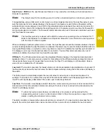
PW Freq.
This value sets the frequency of the pulses that are sent to the PWM valve. The default value is 122
Hz for Raven valves, or a value specified by the valve manufacturer.
Ratio Rate.
Enter a ratio rate value when using a product in an injection system that uses a hand-held spray
gun. The product is injected as a ratio to the amount of carrier product applied. For example, to apply 12.0 oz.
[0.35 L] of product with every gallon of carrier product, enter 12.0 [0.35] in this field. This function works in
manual rate control mode only.
Note:
This value must be set to zero (0) in a non-chemical injection application.
Valve Delay.
Set the valve delay to include a time delay between when the booms are turned on and when the
product nodes start to control the flow rate. Viper Pro activates this delay if the time between turning the boom
on and off is less than 30 seconds.
Note:
A value of zero must be entered if a Fast Close or PWM Close valve is used as the control valve or
when the Valve Type is programmed as a standard valve with an injection system.
Appl (Application) Delay.
The application delay is used with the product chaining feature when advancing to
the next bin in the product chain. Enter the time, in seconds, necessary for the product to travel from the bin to
the boom or spinner. The field computer will use the application delay for each product control channel to
ensure that product application is not interrupted and that the correct target rate is maintained when switching
to the next bin in the product chain.
Dual Pressure Area
Note:
The pressure displays calibrated in this area are designed for monitoring product pressures via a
product control node.
Pressures monitored by the Viper Pro, via electronic pressure transducers, are displayed as P1 (Pressure
Transducer 1) and P2 (Pressure Transducer 2) on the Viper Pro main screen.
Viper Pro displays:
•
All dashes if the node does not detect a pressure transducer.
•
CAL if it detects a pressure transducer but the transducer is not calibrated.
Note:
Pressure readings are provided as display only and do not affect product control. Refer to the
Pressure Transducer section on page 245 for details on calibrating any pressure transducers
connected to the CAN control system.
Summary of Contents for Viper Pro
Page 1: ... Software Version 3 10 Viper Pro Installation Operation Manual ...
Page 42: ...Chapter 3 32 Viper Pro Installation Operation Manual ...
Page 132: ...Chapter 6 122 Viper Pro Installation Operation Manual ...
Page 138: ...Chapter 7 128 Viper Pro Installation Operation Manual ...
Page 180: ...Manual No 016 0171 122 Rev I 170 Advanced Settings and Features ...
Page 194: ...Chapter 9 184 Viper Pro Installation Operation Manual ...
Page 214: ...Chapter 11 204 Viper Pro Installation Operation Manual ...
Page 262: ...Appendix B 252 Viper Pro Installation Operation Manual ...
Page 276: ...Appendix F 266 Viper Pro Installation Operation Manual ...
Page 284: ...Appendix I 274 Viper Pro Installation Operation Manual ...
Page 292: ...Appendix J 282 Viper Pro Installation Operation Manual ...
Page 299: ......

