2
Manual No. 016-0171-122 Rev. I
9
Introduction
Rear Panel
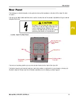
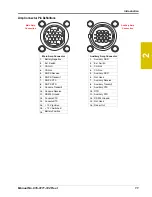
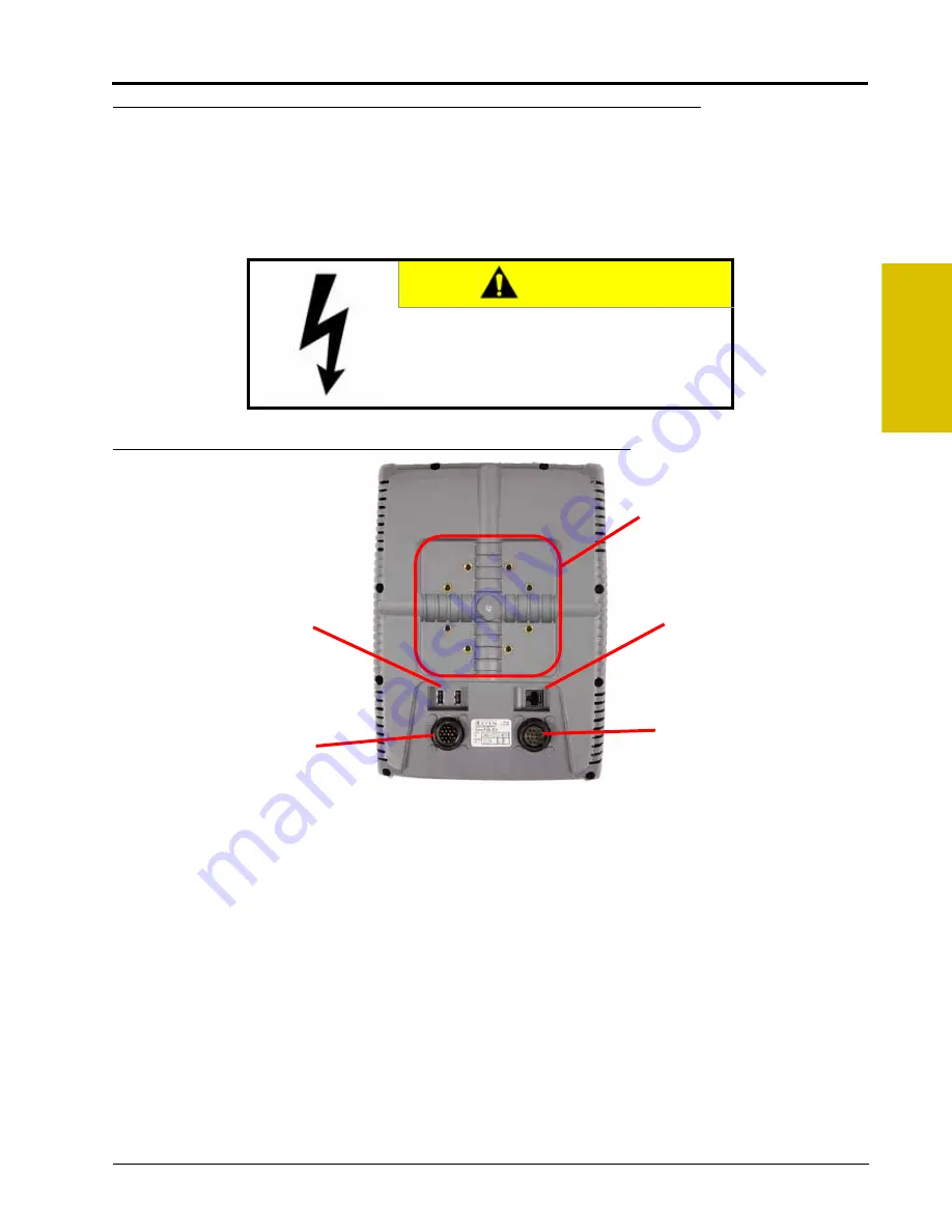
The following is a brief introduction to the ports and connectors available on the back of the Viper Pro field
computer.
The rear panel offers additional USB ports as well as an ethernet port for wireless capabilities using an optional
Slingshot Field Hub.
FIGURE 4.
Viper Pro Rear Panel
The main and auxiliary interface connectors are also located on the back of the Viper Pro.
The field computer part and serial numbers, and revision letter, are printed on the tag located on the back of
the field computer. Please have this information available when contacting customer support.
CAUTION
Damage to the field computer may occur if the
USB ports are used to charge mobile devices
such as cellular phones, tablets, or mp3
devices. The USB ports should only be used for
performing file transfer and maintenance.
Mounting Posts and
Built-In Bracket
Clamps
USB Ports
Ethernet Port
Main Interface
Connector
Auxiliary Interface
Connector
Summary of Contents for Viper Pro
Page 1: ... Software Version 3 10 Viper Pro Installation Operation Manual ...
Page 42: ...Chapter 3 32 Viper Pro Installation Operation Manual ...
Page 132: ...Chapter 6 122 Viper Pro Installation Operation Manual ...
Page 138: ...Chapter 7 128 Viper Pro Installation Operation Manual ...
Page 180: ...Manual No 016 0171 122 Rev I 170 Advanced Settings and Features ...
Page 194: ...Chapter 9 184 Viper Pro Installation Operation Manual ...
Page 214: ...Chapter 11 204 Viper Pro Installation Operation Manual ...
Page 262: ...Appendix B 252 Viper Pro Installation Operation Manual ...
Page 276: ...Appendix F 266 Viper Pro Installation Operation Manual ...
Page 284: ...Appendix I 274 Viper Pro Installation Operation Manual ...
Page 292: ...Appendix J 282 Viper Pro Installation Operation Manual ...
Page 299: ......


