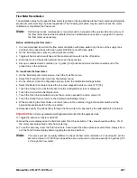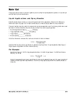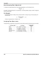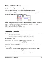
Manual No. 016-0171-122 Rev. I
255
Flow Meter/Encoder Extension Cables
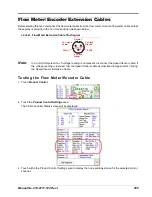
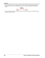
Before starting this test, disconnect the flow meter cable from the flow meter. Hold the flow meter cable so that
the keyway is pointing in the 12 o’clock position as shown below.
FIGURE 2.
Flow Meter Extension Cable Pin Diagram
Note:
In a non-CAN system if a +5 voltage reading is not present, disconnect the Speed Sensor cable. If
the voltage reading is restored, test the Speed Sensor cable as described in Appendix G, Testing
the Speed Sensor Extension Cable.
Testing the Flow Meter/Encoder Cable
1.
Touch
Product Control
.
2.
Touch the
Product Control Settings
area.
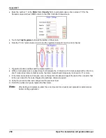
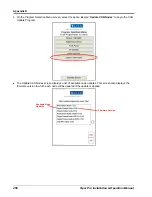
The CAN Controller Status screen will be displayed.
3.
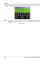
Touch within the Product Control Settings area to display the node settings screen for the selected control
channel.
10 o’clock
Power
2 o’clock
Ground
Keyway
6 o’clock
Signal
5 VDC
5 VDC
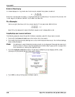
Summary of Contents for Viper Pro
Page 1: ... Software Version 3 10 Viper Pro Installation Operation Manual ...
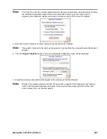
Page 42: ...Chapter 3 32 Viper Pro Installation Operation Manual ...
Page 132: ...Chapter 6 122 Viper Pro Installation Operation Manual ...
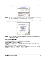
Page 138: ...Chapter 7 128 Viper Pro Installation Operation Manual ...
Page 180: ...Manual No 016 0171 122 Rev I 170 Advanced Settings and Features ...
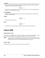
Page 194: ...Chapter 9 184 Viper Pro Installation Operation Manual ...
Page 214: ...Chapter 11 204 Viper Pro Installation Operation Manual ...
Page 262: ...Appendix B 252 Viper Pro Installation Operation Manual ...
Page 276: ...Appendix F 266 Viper Pro Installation Operation Manual ...
Page 284: ...Appendix I 274 Viper Pro Installation Operation Manual ...
Page 292: ...Appendix J 282 Viper Pro Installation Operation Manual ...
Page 299: ......

