4
Manual No. 016-0171-122 Rev. I
35
Initial Set Up and Navigation
2.
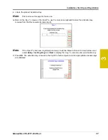
Touch
Yes
. The Re-Address CAN Nodes screen displays.
3.
Cycle the power to the node which will be used to control product channel 1.
Note:
To power cycle a node, temporarily disconnect the logic power connector from the node, wait a
few seconds and reconnect.
4.
Touch the
Next
button on the Viper Pro to cycle the next product node in the system.
5.
Repeat steps step 3 and step 4 until all product control nodes in the system have been re-addressed.
6.
Touch
Finish
.
7.
Touch
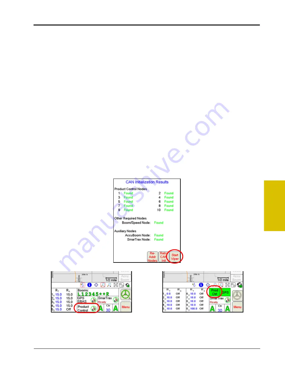
Start Viper
when all the product nodes in the system display as ‘Found.’
Note:
If the field computer is enabled to receive web notifications via the Slingshot server, a prompt or
dialogue may be displayed after the Start Viper button is selected and the Main screen is
displayed. Refer to the Wireless File Transfer section on page 193 for more information.
Configuring a Product Controller Node
Each Raven product controller node may be configured for up to five control channels to provide controls for
individual product control features on the CANbus. It may be necessary to disable control channels on the
product controller node if specific channels will not be used or if additional control nodes will be connected to
the CANbus network to provide control for specific hardware.
Refer to the following procedures to set up the product controller node on the CANbus network.
1.
Power up the Viper Pro field computer select the
Start Viper
option on the CAN Initialization Results
screen.
2.
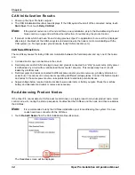
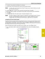
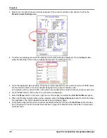
From the Viper Pro main screen, touch the
Product Control
button.
or
Summary of Contents for Viper Pro
Page 1: ... Software Version 3 10 Viper Pro Installation Operation Manual ...
Page 42: ...Chapter 3 32 Viper Pro Installation Operation Manual ...
Page 132: ...Chapter 6 122 Viper Pro Installation Operation Manual ...
Page 138: ...Chapter 7 128 Viper Pro Installation Operation Manual ...
Page 180: ...Manual No 016 0171 122 Rev I 170 Advanced Settings and Features ...
Page 194: ...Chapter 9 184 Viper Pro Installation Operation Manual ...
Page 214: ...Chapter 11 204 Viper Pro Installation Operation Manual ...
Page 262: ...Appendix B 252 Viper Pro Installation Operation Manual ...
Page 276: ...Appendix F 266 Viper Pro Installation Operation Manual ...
Page 284: ...Appendix I 274 Viper Pro Installation Operation Manual ...
Page 292: ...Appendix J 282 Viper Pro Installation Operation Manual ...
Page 299: ......

