4
Manual No. 016-0171-122 Rev. I
45
Initial Set Up and Navigation
Valve Cal 2 (Optional)
The valve cal 2 value may be used to fine tune control valve response and reduce application rate oscillations
when using a Fast Close, PWM or PWM Close control valve.
Fast Close Valves.
When using a fast close valve to control product application, valve cal 2 is utilized to
enable a high resolution rate control for lower application rates. Enter a non-zero value for the time, in
milliseconds, which the valve will be fully opened before switching into high resolution control. For example, a
value of 200 will give the valve a 200 millisecond “burst” at a full 12V to open the control valve from the closed
position before resuming product rate control. A zero value will disable this feature.
Note:
When used with a Fast Close valve, the valve cal 2 feature requires product node software version
1.40 or higher for operation.
PWM or PWM Close Valves.
The valve cal 2 feature is not used with all systems or application equipment.
Refer to the OEM operation manual for instructions on using the valve cal 2 feature with PWM or PWM Close
control valves.
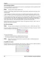
Dual Loop Control Cals
The following calibration values will replace the valve cal and valve cal 2 values if the dual loop control feature
is enabled. See the
section on page 137 for details on the dual loop control mode. Refer to
the
Node Feature Settings Screen (Page 2)
section on page 136 for information on enabling the dual loop
control feature.
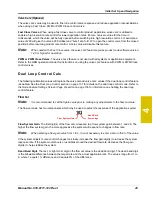
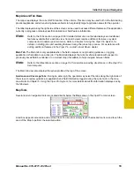
Flow Cal
Note:
It is recommended to set the Sgain value prior to making any adjustments to the flow cal value.
The flow cal value has two components which may be used to adjust the response of the application system.
Flow System Gain.
The first digit(s) of the flow cal correspond to a flow system gain between 1 and 99. The
higher the flow system gain, the more aggressive the system will respond to changes in flow rate.
Note:
When entering a flow gain value from 1 to 9, it is not necessary to enter a zero in front of the value.
If the system adjusts to rate control changes too slowly, increase the flow gain digit(s) to increase the system
response rate. If the system overshoots or oscillates around the desired flow rate, decrease the flow gain
digit(s) to help stabilize the system.
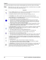
Dead Band Digit.
The last, or right most, digit in the flow cal value is the dead band digit. The dead band digit
is the allowable difference between the target rate and the actual application rate. The values range from 1 to
9, where 1 equals 1% difference and 9 equals 9% of the difference.
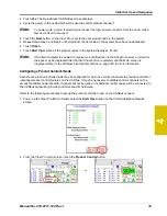
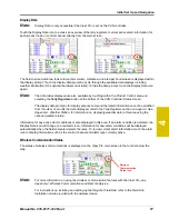
Flow System Gain
Dead Band
Percentage
103
Summary of Contents for Viper Pro
Page 1: ... Software Version 3 10 Viper Pro Installation Operation Manual ...
Page 42: ...Chapter 3 32 Viper Pro Installation Operation Manual ...
Page 132: ...Chapter 6 122 Viper Pro Installation Operation Manual ...
Page 138: ...Chapter 7 128 Viper Pro Installation Operation Manual ...
Page 180: ...Manual No 016 0171 122 Rev I 170 Advanced Settings and Features ...
Page 194: ...Chapter 9 184 Viper Pro Installation Operation Manual ...
Page 214: ...Chapter 11 204 Viper Pro Installation Operation Manual ...
Page 262: ...Appendix B 252 Viper Pro Installation Operation Manual ...
Page 276: ...Appendix F 266 Viper Pro Installation Operation Manual ...
Page 284: ...Appendix I 274 Viper Pro Installation Operation Manual ...
Page 292: ...Appendix J 282 Viper Pro Installation Operation Manual ...
Page 299: ......

