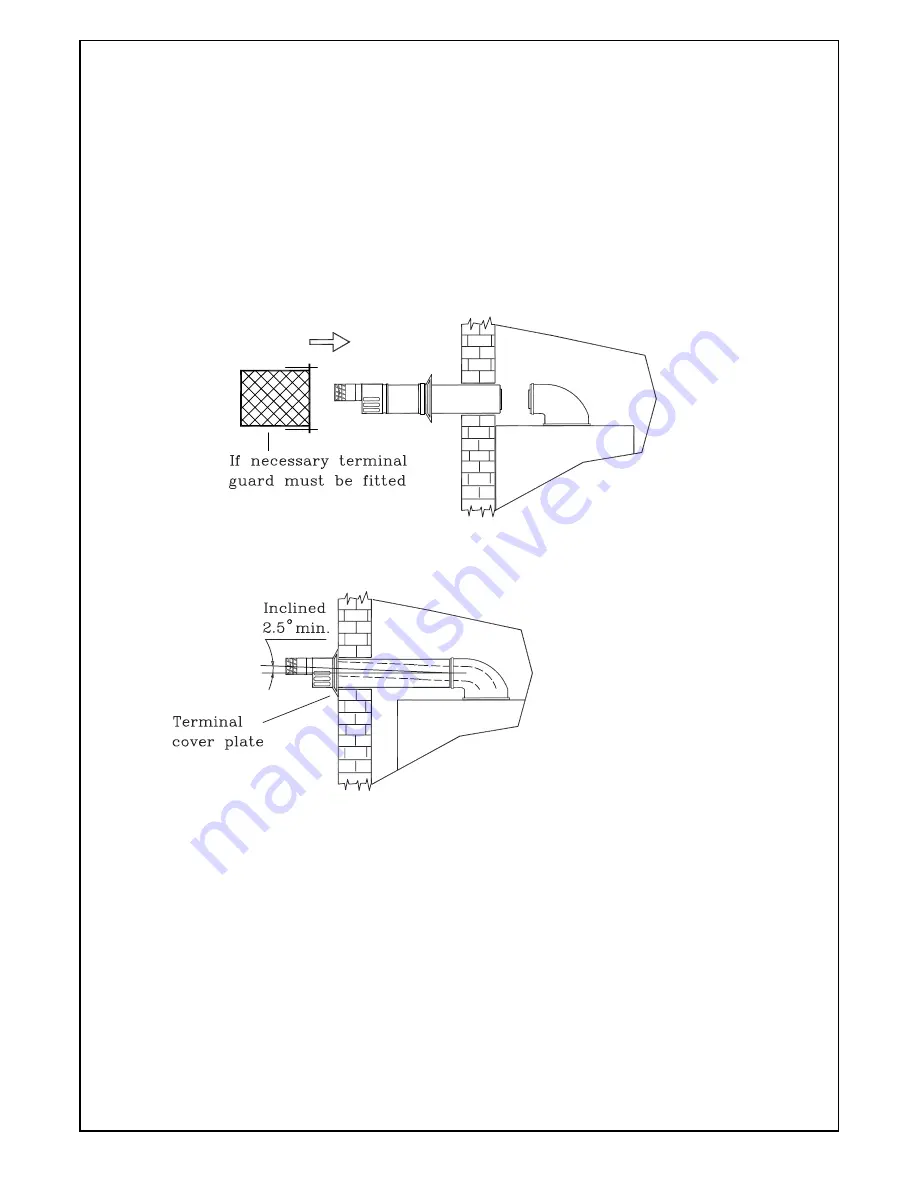
Fig. 23
Fig. 24
19
5.5.4
Insert the flue assembly into the wall, being
careful to make sure that the outer air duct
comes flush to the inner surface of the wall.
5.5.5
Lift the boiler on to the wall, locating onto the
fixing jig wall bracket.
5.5.6
Working above the boiler pull the flue exhaust
duct towards the boiler in order to engage tube
61 into its header 57 (Fig. 21-22).
Position flue into elbow header and push to
locate inner and outer flue correctly ensuring a
good seal is made with or rubber seal.
5.5.7
Fit terminal cover plate (fig. 23).
5.5.8
Extensions kits are available to order for flue
extension of up to 2.5 metres total length.
Make sure flue slopes 2.5° down
towards the boiler that is 45 mm/m
fall per metre of the flue length.
Summary of Contents for 780 Series
Page 2: ......
Page 7: ...7 Fig 3 OVERALL DIMENSION ...
Page 34: ...34 Fig 45 Fig 44 Fig 46 ...
Page 36: ...36 Fig 48 Fig 47 Fig 49 Fig 50 Fig 51 ...
Page 42: ...Fig 59 42 SECTION 9 ELECTRICAL SYSTEM DIAGRAM ...
Page 46: ...79 83 105 46 50 27 16 39 17 2 22 100 1 4 5 11 8 SECTION 11 ...
Page 49: ...49 ...
Page 50: ...COD 0017LIB06010 2 03 2010 ...


