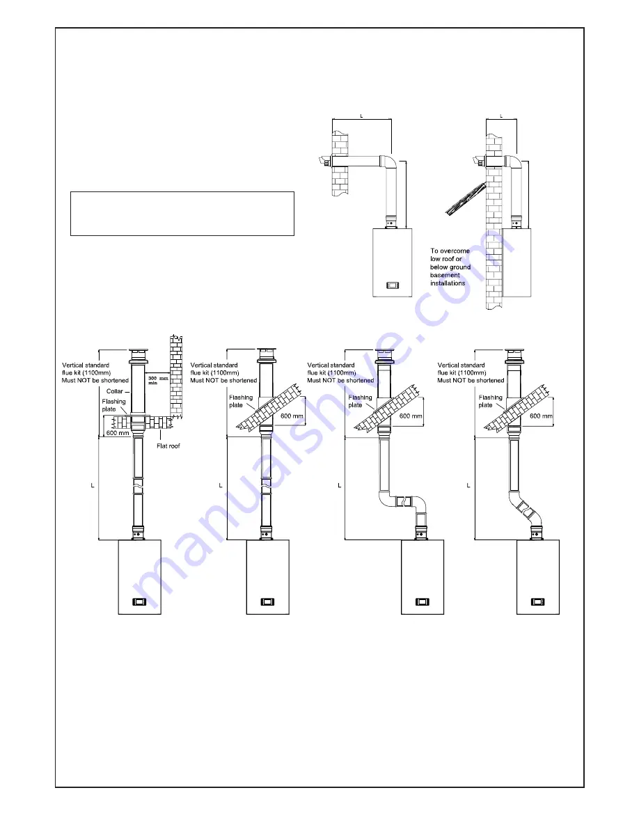
L + L = 8m Max
Fig. 19
Straight Flue Straight Flue Offset Flue Offset Flue
L = 12 m Max L = 12.0 m Max L = 10 m Max L = 11 m Max
plus Terminal plus Terminal plus 2 bend 90° plus 2 bend 45°
and Terminal and Terminal
Fig. 20
32
5.12 VERTICAL FLUE INSTRUCTION ONLY (Fig. 19-20-21)
SEE SECT. 4.10 FOR PERMISSIBLE FLUE POSITION
IN-LINE FLUE BEND - 1000 mm MUST BE DEDUCTED FROM OVERALL LENGTH FOR EACH 90° BEND
OBTUSE FLUE BEND - 500 mm MUST BE DEDUCTED FROM OVERALL LENGTH FOR EACH 135° BEND.
The vertical flue kit is intended for use where
a horizontal flue outlet is not possible or desired.
The vertical flue can be used either with a flat roof
or a pitched roof (maximum pitch 60°).
Where a straight vertical flue is not possible or desired,
an offset vertical flue can be used in conjunction with
a side horizontal flue extension piece and in-line
135°/90° flue bend (fig. 19).
Proceed with installation as detailed in section 5
ignoring all references to horizontal flue installations.
Use adhesive tape to attach the template to the wall,
making sure that the centre line is vertical and that the
flue centre line is virtually below the point at which the
flue will exit the roof.
- Ensure that the maximum permissible flue
permissible flue
length is not exceeded (fig. 20 and see table 5).
length is not exceeded (fig. 20 and see table 5).
- Mark the two wall fixing bolt holes
- Mark the two wall fixing bolt holes
- Detach the template from the wall.
- Detach the template from the wall.
- Use a 10 mm dia. drill to make the 2 holes.
- Use a 10 mm dia. drill to make the 2 holes.
- Insert plastic expansion plug.
- Insert plastic expansion plug.
- Screw in the two coach bolts.
- Screw in the two coach bolts.
- Position the flue sample point starter (straight
- Position the flue sample point starter (straight
flue header which must be fitted) and fix the
flue header which must be fitted) and fix the
securing screw on the flue adaptor appliance
securing screw on the flue adaptor appliance
(fig. 22 item 66), and ensure that the gasket
is correctly fitted.
Important: Make sure that the inner 60
mm diameter of the straight flue header
is inserted fully into the flue manifold,
and the flue manifold rubber seal is
correctly fitted. (Fig 22 item 65)
IMPORTANT NOTES : For greater flue
length see
twin flue or concentric 80/125
flue instructions
Summary of Contents for CS 80 T
Page 2: ...2 ...
Page 21: ...21 4 10 FLUE TERMINAL POSITION ...
Page 54: ...10 ELECTRICAL SYSTEM DIAGRAM 54 Fig 56 ...
Page 55: ...55 11 SPARE PARTS Fig 57 ...
Page 61: ...61 ...
Page 62: ...62 ...
Page 64: ...64 FLOWCHART FOR CO LEVEL AND COMBUSTION RATIO CHECK ON COMMISSIONING A CONDENSING BOILER ...
Page 65: ...65 12 1 ANALYSER CHECK LIST ...


