necessary to prevent damage to the system,
and to the building, in the event of the
system remaining inoperative during frost
conditions.
-
Explain the function and the use of the
boiler, the summer/winter button, the
ON/OFF switch and the reset of the digital
display.
- Explain and demonstrate the function of the
temperature controls, radiator valves etc. for
the economic use of the system.
- If an external time clock is fitted, then draw
attention to the digital time.
- Stress the importance of regular servicing
by a qualified Heating Engineer and that a
comprehensive service should be carried
out AT LEAST ONCE A YEAR.
- Fill in the Benchmark log book and leave
completed with the customer.
- Explain to the user how to isolate the
user how to isolate the
appliance from the gas, water and
appliance from the gas, water and
electricity supplies an
electricity supplies and the locations of
all drain points.
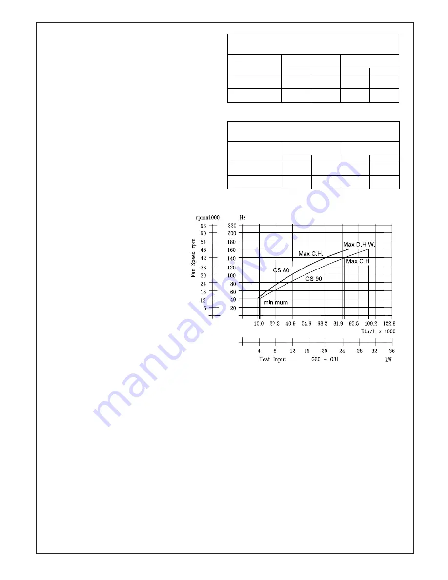
RATIO BETWEEN FAN SPEED
AND HEAT INPUT
Fig. 38
Range rating regulation of Central Heating
C.H. regulations
Heat input (kW)
Fan speed (rpm)
CS 80
CS 90
CS 80
CS 90
Maximum setting
20
24,5
4200
4200
Minimum setting
3,7
4,1
1300
1300
TABLE 11/A
Range rating regulation of Domestic Hot Water
D.H.W. regulations Heat input (kW)
Fan speed (rpm)
CS 80
CS 90
CS 80
CS 90
Maximum setting
25,4
30,1
4800
4800
Minimum setting
3,7
4,1
1300
1300
TABLE 11/B
6.15 RANGE RATING CENTRAL HEATING
OR/AND DOMESTIC HOT WATER
The boiler comes set, in Central heating,
at the MID RANGE of its output.
The boiler has already been adjusted by the
been adjusted by the
manufacturer during production. If the
manufacturer during production. If the
adjustments need to be made again, observe
adjustments need to be made again, observe
the following procedures.
the following procedures.
The adjustment to fan speed must be
The adjustment to fan speed must be
strictly in the sequence indicated, by
strictly in the sequence indicated, by
qualified personnel only.
qualified personnel only.
To check max fan speed, see tables 11/A
To check max fan speed, see tables 11/A
and 11/B:
and 11/B:
- Press P button (item 8 fig. 1) for 3
- Press P button (item 8 fig. 1) for 3
seconds to enter in menu.
seconds to enter in menu.
- Use arrow up and arrow down buttons
- Use arrow up and arrow down buttons
(item 3 and 4 fig. 1), to select BOIL.
(item 3 and 4 fig. 1), to select BOIL.
- Press reset and the up arrow button
- Press reset and the up arrow button
together (item 2 and 3 fig. 1) and then
together (item 2 and 3 fig. 1) and then
press the enter button.
press the enter button.
- Use arrow up and arrow down buttons
- Use arrow up and arrow down buttons
(item 3 and 4 fig. 1) to select the
(item 3 and 4 fig. 1) to select the
followings options:
followings options:
- PM1 CH max fan speed.
- PM1 CH max fan speed.
- PM2 DHW max fan speed.
- Press enter (item 1 fig. 1) to select
CH or DHW fan speed.
Adjust if necessary.
6.16 TEST MODE
It is possible to activate the test mode
function by pressing the arrow up and the
the arrow up and the
arrow down buttons, (item 3 and 4 fi g. 1)
arrow down buttons, (item 3 and 4 fi g. 1)
for 5 seconds.
for 5 seconds.
Press the arrow up and the arrow down buttons
Press the arrow up and the arrow down buttons
to set the maximum or minimum fan speed.
to set the maximum or minimum fan speed.
The function is enabled for maximum 15
The function is enabled for maximum 15
minutes and it has priority on D.H.W. mode.
minutes and it has priority on D.H.W. mode.
Press reset to esc test mode.
Press reset to esc test mode.
6.17 INSTRUCTING THE USER
6.17 INSTRUCTING THE USER
After completion of the installation and
After completion of the installation and
commissioning of the system, the installer
commissioning of the system, the installer
should hand over to the Householder by
should hand over to the Householder by
taking the following actions:
taking the following actions:
- To the Householder explain his/her
- To the Householder explain his/her
responsibilities under the “Gas Safety
responsibilities under the “Gas Safety
Regulations 2000”.
Regulations
2000”.
- Explain and demonstrate the lighting
- Explain and demonstrate the lighting
and shutting down procedures.
and shutting down procedures.
- Show the user the location of the filling
valve and how to top-up the system
pressure correctly.
- Explain the operation of the boiler
including the use and adjustment of
ALL system controls which should be
fully explained to the Householder. This
will ensure the optimum fuel economy
for the household requirements of both
heating and hot water consumption.
Advise the User of the precautions
43
Summary of Contents for CS 80 T
Page 2: ...2 ...
Page 21: ...21 4 10 FLUE TERMINAL POSITION ...
Page 54: ...10 ELECTRICAL SYSTEM DIAGRAM 54 Fig 56 ...
Page 55: ...55 11 SPARE PARTS Fig 57 ...
Page 61: ...61 ...
Page 62: ...62 ...
Page 64: ...64 FLOWCHART FOR CO LEVEL AND COMBUSTION RATIO CHECK ON COMMISSIONING A CONDENSING BOILER ...
Page 65: ...65 12 1 ANALYSER CHECK LIST ...


