47
8.6
TO REMOVE/ REPLACE THE
ELECTRODES (Fig.37)
Remove the front panel (fig. 39).
Remove the ignition and/or sensing lead
plug.
Unscrew the two securing screws and put
them into a suitable container so that they
don’t get lost.
Withdraw the Spark electrode and/or
Sensing electrode carefully from the burner
cover being careful not to damage the
seal.
Replace with a new
Replace with a new electrode in reverse
order. Ensure the gap is correct and there
is a good seal when replaced (always
fitting a new gasket).
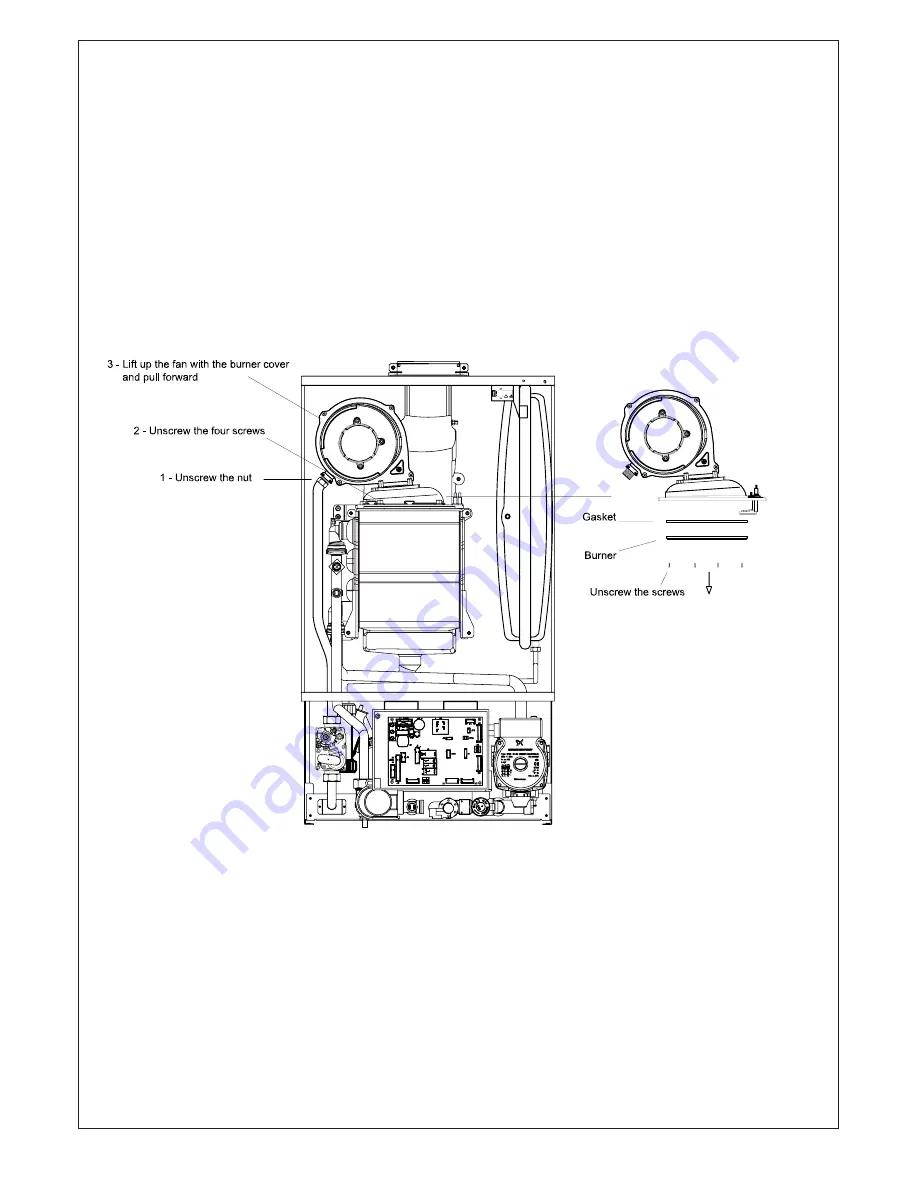
8.7 TO REMOVE/REPLACE THE BURNER
(FIG.43)
Remove the front panel (fig. 39).
Unscrew the gas pipe nut and remove the
retaining clip. Detach the connectors from
the fan.
the fan.
U
Unscrew the screws to the burner cover
and remove the cover with the fan.
To remove the burner, unscrew the screws
in the lower cover side.
Replace in reverse order (always fitting a
new gasket).
Fig.43
8.8
TO REMOVE/REPLACE THE MAIN HEAT
EXCHANGER
Remove the front and bottom panels
(fig. 39-40).
Drain the boiler CH circuit and drain the
DHW circuit. Follow the instructions to
Follow the instructions to
remove the burner (sect. 8.7). Pull down to
remove the burner (sect. 8.7). Pull down to
remove the condens
remove the condense pipe on the bottom
of the heat exchanger.
Disconnect the flow
and return pipes at the heat exchanger.
Loosen the four heat exchanger securing
screws and clamps then carefully ease the
heat exchanger out.
CAUTION :
There will be water in the heat
exchanger.
Replace in reverse order, always use new
O-ring sea
O-ring seals.
Summary of Contents for CS 80 T
Page 2: ...2 ...
Page 21: ...21 4 10 FLUE TERMINAL POSITION ...
Page 54: ...10 ELECTRICAL SYSTEM DIAGRAM 54 Fig 56 ...
Page 55: ...55 11 SPARE PARTS Fig 57 ...
Page 61: ...61 ...
Page 62: ...62 ...
Page 64: ...64 FLOWCHART FOR CO LEVEL AND COMBUSTION RATIO CHECK ON COMMISSIONING A CONDENSING BOILER ...
Page 65: ...65 12 1 ANALYSER CHECK LIST ...


