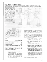
Fig. 6
Terminal
position for fan assisted boiler
(minimum distance)
A
- Directly below an open window or other
opening (e.g. air brick)
B
- Below gutters, soil pipes or drain pipes
C - Below eaves
D
- Below balconies or car port roof
E
- From vertical drain pipes and soil pipes
F
- From internal or external corners
mm
300
25
4.8
25
25
25
25
4.8.1
G
- Above ground or below balcony level
300
H
- From a surface facing a terminal
600
I
From a terminal facing a terminal
1200
4 . 8 2
J
- From an opening in the car port (e.g. door
window) into dwelling.
1200
K
- Vertically from a terminal on the same wall
1500
L
Horizontally from a terminal on the same wall
300
NOTE:
The flue must be terminated in a place not
likely to cause a nuisance.
4.6.2
A concentric vertical flue kit is available, for
flueing applications up to a maximum height
of 4.0 metres.
For further details see vertical flue installa-
tion instructions.
4.7
4.7.1
AIR SUPPLY
The following notes are intended for general
4.8.3
guidance.
The room sealed fan flued boiler does not
require a permanent air vent for combustion
air supply.
Where installed in a cupboard or compart-
ment ventilation is not required.
CONDENSATE DRAIN
A
condensate drain is provided on the boiler.
This drain must be connected to a drainage
point. All pipework and fittings in the conden-
sate drainage system MUST be made of plas-
tic - no other materials may be used.
Discharge of condensate DD 189:1990.
The drain outlet on the boiler is standard
3/4" (21.5 mm) push fit overflow pipe.
NOTE: Condensate drain pipework must
never be less than 15 mm.
Important:
any external runs must be car-
ried out in 1 1/4 (32 mm) wastepipe.
A fall of 2.5” (45 mm/m) all runs must have.
WATER CIRCULATION (central heating)
Detailed recommendations are given in BS
6798 5449.1.1977 (for smallbore and micro-
bore central heating systems). The following
notes are given for general guidance.
Pipework
Copper tubing to BS 2671 1.1.1971 is rec-
ommended for water pipes. Jointing should
be either with capillary soldered or with
compression fittings.
Where possible pipes should have a gradi-
ent to ensure air is carried naturally to air
release points and water flows naturally to
drain taps. It should be ensured as far as
possible that the appliance heat exchanger
is not a natural collecting point for air.
Except where providing useful heat, pipes
should be insulated to prevent heat loss and
to avoid freezing. Particular attention should
be paid to pipes passing through ventilated
spaces in roofs and under floors.
The water through the appliance heat
exchanger circuit must exceed the min. 1.84
gals/min. (503 It/h) when the burner is firing. It
is important to ensure that this rate is achieved
when sections of the system are shut off either
manually or by automatic controls. Therefore
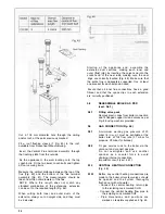
a by-pass must be fitted to the system (15
mm min.) (Fig. 6A).
If the volume of circulating water is too low,
the boiler water temperature will rise too
rapidly. This could cause noise in the system
or even cause the safety thermostat to trip.
12
Summary of Contents for CSI 85
Page 26: ...27...
Page 42: ......
Page 45: ...SECTION 9 ELECTRICAL SYSTEM DIAGRAM Fig 94 46...
Page 46: ...47...
Page 47: ......
Page 48: ...49...
Page 52: ......
Page 55: ...Chartists Way Morley Leeds LS27 9ET Telephone 0113 252 7007 Tfax 0113 238 0229...


