4.
Electrical Inputs and Outputs
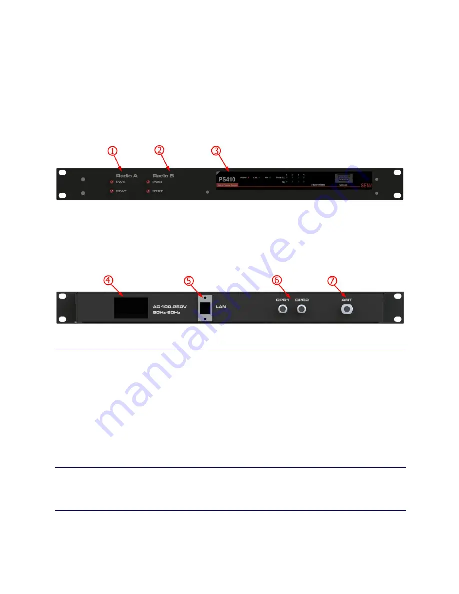
The front of the <bs_pn> has these features:
1. Radio A Power and Status Indicators
2. Radio B Power and Status Indicators
3. SENA PS410 Front Panel
The rear of the <bs_pn> has these features:
4. IEC C14 Power Inlet
5. RJ-45 Network I/O Connector
6. TNC GPS Jack (2)
7. N-Type RF Jack
4.1
LEDs
The status LEDs visually show the current status of the radio, as well as terminal server
power and activity.
Status LED
The STAT LED will indicate unit function, and will vary according to the radio module
within the RV-SMB.
Power LED
The STAT LED will indicate unit function, and will vary according to the radio module
within the RV-SMB.
4.2
AC Power
AC power is supplied via the IEC C14 power inlet. The power inlet is switched, and
contains one replaceable 6A fuse.
4.3
Network I/O
The Network I/O is used with an RJ-45 terminated patch cable to connect to a network
10-BaseT or 100-BaseTX capable switch.


