
Compliance with current legislation regarding Oil tanks and the siting thereof as directed by the
Building Regulations Parts J & L.
The fitting of Safety Fire Valves as directed by the Building Regulations and by Snughome Ltd.
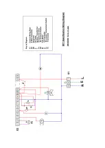
This Equipment must be earthed.
This equipment should be wired from a double pole switched fused spur having a minimum contact
gap of 3mm, rated at 5 amps
This Equipment is only suitable for the appliance for which it has been designed..
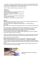
Site Vetting;
Before any decision to convert any appliance the site and the appliance
must
be
inspected. Failure to do this will generally lead to a poor installation and a dissatisfied Customer. On
arrival at the site have a look up at the chimneys and if possible check from a couple of directions.
See if there is any soot stain down the sides of the chimney pots. Have a look at the surroundings of
the chimney particularly angled close roofs, over hanging branches and trees, geographical position
(i.e. down draught).
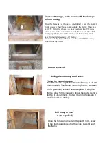
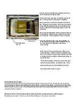
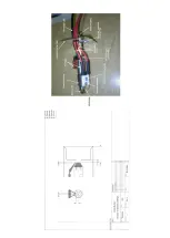
COOKER POSITION -- Although this cooker can be turned off and on as required it should
be considered as normally constant running & will get hot. Therefore it should be mounted
on a solid non-combustible base and a minimum clearance of 100 mm should be left on
either side of the appliance when combustible materials are placed close to it, for example
kitchen units. Any other surfaces adjacent to the cooker should be of non-combustible
materials.
This conversion does not need free area around the sides of the cooker for air supply as it receives
combustion air through the bottom of the outer door of the cooker..
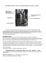
Installation of this Equipment must be carried out by suitably
OFTEC
qualified/ trained personnel,
That have also received training from Snughome in this type of conversion.
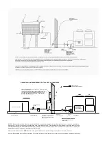
1. This is a fan assisted burner and runs at 32,000 Btu/hr 9.4 Kw maximum when burning, the air
requirements for this must be taken into account when determining the necessary
ventilation.
2. Extractor fans when fitted should be positioned as far away from the flue as possible
and
should have a sufficient dedicated air supply. To undertake a test, the oil fired appliance should
be set in operation at maximum setting and the doors and windows closed. The extractor fan
should then be run at its maximum setting. The oil fired heating appliance should be observed to
operate satisfactorily both before and after the fan is switched on.
2. It is preferable that the air supply for the extractor fan should be located where it can serve
the fan without the air stream passing close to the oil fired appliance.
3. As this appliance draws its air through the outer fire box door this must not be obstructed in
any way
Oil fired appliances MUST NOT draw combustion air from a garage.
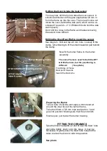
FLUES & CHIMNEY TERMINATION
Building Regulations “J”. L1 & L2
The new approved documents J, and the “Competent Persons legislation both came into force on
All installations, chimneys, flue’s , building work etc, must comply with the new legislation.
Suitable Flues and liners should be used in accordance with Building Regulations
Document J pages 18 - 21, and page 52
An Anti Down Draught Cowl (that conforms to British Standards)
SHOULD BE FITTED.
Possibly the best one on the market today is the
O.H. COWL
. Down draught will not go away it has
to be eliminated.


