background image

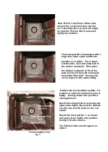
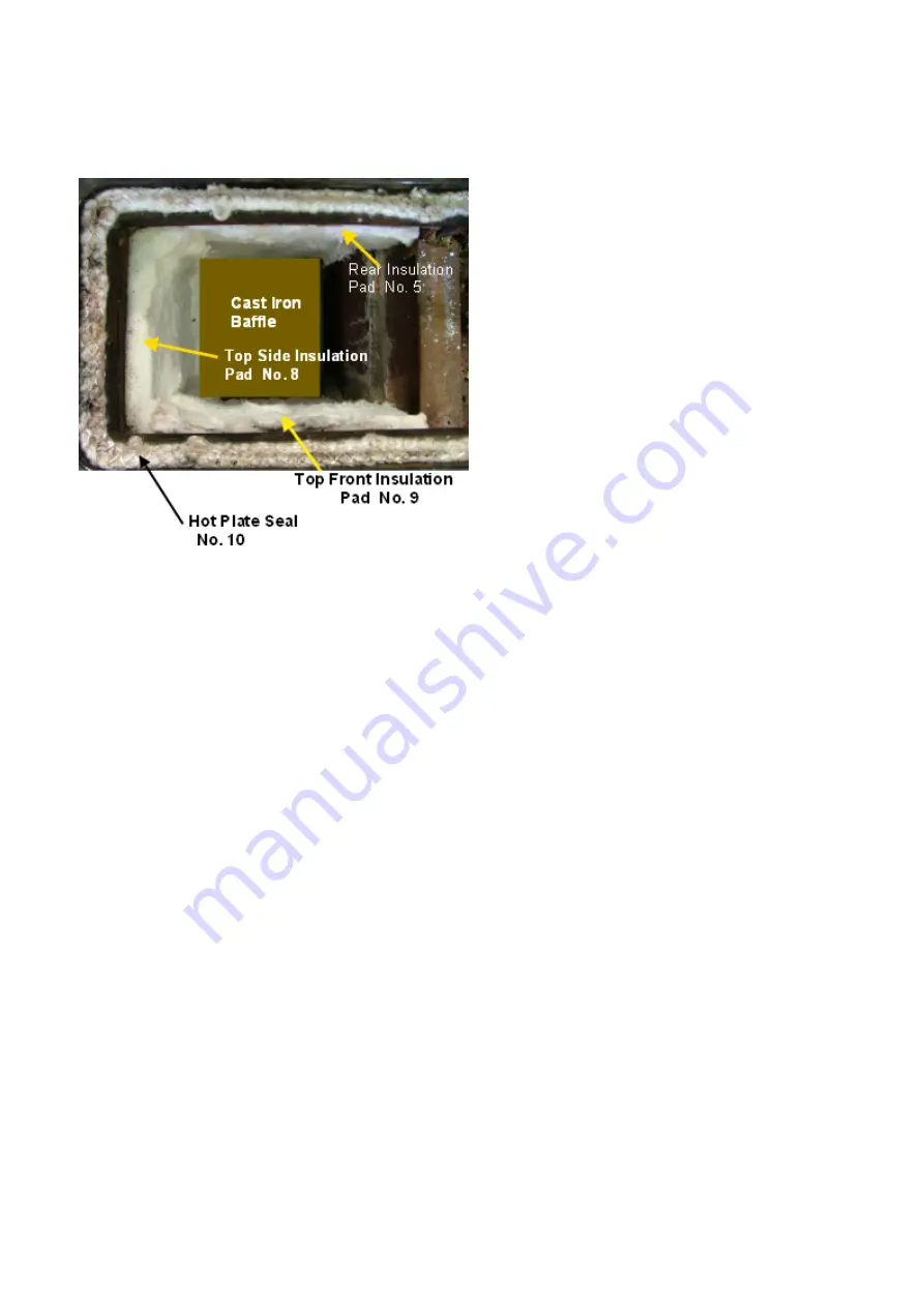
Fit the cast iron baffle into position with the
front markings facing forward.

Then  place  the  top  side  insulation  pad  part
No. 8  into position, pressing it in tightly.

Now press the Top Front Insulation Pad Part
No. 9 tightly into position. Press the top edges
of the blankets back as far as possible so as
not to restrict the air passage-ways under the
hot plate.

Now glue the Hot Plate 15 mm seal part No. 10
into position with the tales at the cool end of
the hot plate, ensuring that it seals correctly.

Glue the short 15 mm rope seal part No. 11

to the underside ridge on the hot plate. Place
the  hot  plate  into  position  and  press
down firmly.

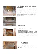
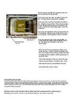
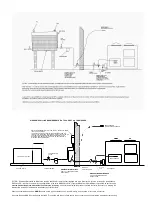
Drill a hole 15 mm into the top of the oven

under the flue.  Fit the 15-22 mm adaptor into
the 15 mm hole and seal, then put the 22 x 300
mm pipe into the adaptor, allowing the pipe to
go up the flue.

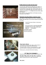
Fit the flue adaptor to the top of the flue box,

and seal into position, using fire clay.  Then

place the flue cover into position and seal.

Then fit the flue to the cooker.

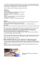
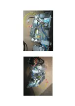
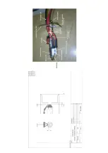
Connecting the oil pipe.

Hold the end of the 6 mm bundy tube and gently pull up and across to connect to the oil pump,

using jointing compound and tightly securely. Note – because the pump is flexibly mounted make

sure the joint is TIGHT and also that the bundy tube doesn’t reverberate against the fan housing

which would create noise. Trim and bend the other end of the pipe and make into the oil filter

using the fitting supplied.

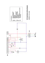
Wiring. Connect the terminal block to the feed flex and prepare for switching on.

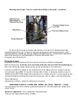
Bleeding the oil pipe. There is a small bleed fitting on the pump- see photo-

Summary of Contents for 200

Page 1: ...IRED COOKERS RAYBURN Models OF7 G7 200 209 INSTALLATION Servicing Commissioning ISSUE No 3 DATE 1st September 2007 Snughome Cookers Ltd 2 Cromwell Road Shaw Newbury RG14 2HL Tel No 01635 846787 Fax No 01635 846787 No 210955 Supplied by ...

Page 2: ...e top burner manufacturers Only use components supplied by SNUGHOME Ltd as these have been specifically designed for this purpose NO LIABILITY WILL BE ACCEPTED IF OTHER THAN SNUGHOME PARTS ARE FITTED It has been designed to use most common fuel oils All components are manufactured from well proven materials and should give reliable service with improved economy Noise has always been a problemwith ...

Page 3: ...hrough the bottom of the outer door of the cooker Installation of this Equipment must be carried out by suitably OFTEC qualified trained personnel That have also received training from Snughome in this type of conversion 1 This is a fan assisted burner and runs at 32 000 Btu hr 9 4 Kw maximum when burning the air requirements for this must be taken into account when determining the necessary venti...

Page 4: ... mild steel oil storage tank should be manufactured to BS 799 Part 5 Plastic oil tanks are covered by OFTEC standard OFST100 The minimum recommended oil tank size is 1400 litres 300 gallons Codes of practice governing installation are covered by BS5410 Part 1 Should a lift pump be required with the new building regulations and current trends in health and safety it is recommended that the oil lift...

Page 5: ...upply pipes and the cast iron base plate it sits on This assumes you have already disconnected the oil gas supply to the cooker or have had it professionally disconnected by an approved engineer OFTEC CORGI registered Remove the pipe that enters the cooker through the side panel You may leave any oil stop valve or KBB fire valve in place and any sensor inside the cooker may be simply moved out of ...

Page 6: ...nly Vacuum out the area underneath to stop swarf from being sucked into the burner Drilling the mounting stud holes Drill to tap to 6mm studs supplied Fitting the mounting plate Once the holes are drilled and tapped 6 mm screw in the studs supplied so that they just pass through the frame When the burner is positioned in the firebox 2 x 6 mm studs locate it The Burner mounting Frame as seen in the...

Page 7: ...ion pad behind the clamp 150 mm Thermostat Capillary 6 mm Front Edge of Frame Must point forwards toward the blast tube The same Frame is used for both the OF7 OF22 burners but the positioning is different See photo Now fit the burner frame to the burner assembly Preparing the Burner Take a tube of silicone and apply a thick bead all around the inner face of the burner frame Take the 35mm x 725 mm...

Page 8: ...ess the blanket outwards to fill all the gaps but try and keep the hole equal around the blast tube The hole size can be larger to take up the fitting Position the rear insulation pad No 5 in position as shown in photo and press in tightly coming down onto pad No 4 sealing the back Now fit the side pad No 6 as shown and again press tightly into position Making sure the rear and the front corners a...

Page 9: ...flue Fit the 15 22 mm adaptor into the 15 mm hole and seal then put the 22 x 300 mm pipe into the adaptor allowing the pipe to go up the flue Fit the flue adaptor to the top of the flue box and seal into position using fire clay Then place the flue cover into position and seal Then fit the flue to the cooker Connecting the oil pipe Hold the end of the 6 mm bundy tube and gently pull up and across ...

Page 10: ...to the control box It may go to LOCK OUT initially as the oil pump is full of air Bleed until oil is constant note the lock out button stays RED for around 2 minutes after it locks ot Note also that the burner is TIMED and will NOT FIRE initially until it has done its 3 minutes off cycle You can speed up the off period initially by switching the power off to the burner then on again this fools the...

Page 11: ...0 100 ppm CO2 8 8 9 0 This will change when hot Co CO2 0 0003 0 0008 It may be necessary to adjust the combustion to these figures by setting the air lever as detailed above When the cooker is hot and up to temperature this should give HOT COMBUSTION FIGURES With the cover plate in position Co 30 100 ppm Co CO2 0 0003 0 0008 If not it may be necessary to adjust accordingly After Setting the combus...

Page 12: ......

Page 13: ......

Page 14: ......

Page 15: ......

Page 16: ...er 1 X01 807 198 1 4 B S P x 6m m c om pres s ion c oupling 1 X01 739 275 1 4 B S P x 10m m c om pres ion c oupling 3 X03 S P 06 0 0640 6m m x 40m m S tuds 2 X05 06 S W 6m m W ings Nuts 2 X04 S P 0612 6m m F lat was hers 2 1 0m m 3 c ore c able x 3m long fem ale 3pin plug 1 E 03 TF V 90 30 TF V F IRE V A LV E x 3m 1 E 90 301 801 401 00 6m m x 80m m bleed tube 1 E 90 300 801 306 00 25m 6m m x 250m ...

Page 17: ......

Page 18: ... REQUIREMENTS IF A TOP OUTLET OIL TANK IS USED FILTER A strainer filter should be fitted to the tank An additional 5 10 micron filter supplied with kit is fitted just be fore the oil control on the appliance FIRE VALVES In order to comply with current legislation a fire valve KBB 65 0r simila r Type available from OILWARM but not supplied as part of the kit must be fitted at the point where the fu...

Reviews: