background image

Place the cooker in the intended position and lift out of the
surface ground hotplate, checking that the joint between the
underside of the hob and the top of the cooker are intact. 
Any joints which have opened should be made good with fire
cement provided.
Check that the boiler/cooker flueway dampers operate correctly
by turning the knob on the front plate adjacent to the top left
hand corner of the roasting oven door.

NOTE: IT IS NOT VISUALLY POSSIBLE TO SEE THE
BOILER DAMPER AND THIS SHOULD BE CHECKED BY
FEELING THROUGH THE HOTPLATE APERTURE TO THE
BACK OF THE COOKER. THE COOKER DAMPER SPINDLE
OPERATES THE BOILER DAMPER WHICH CAN BE FELT
BY INSERTING HAND INTO FLUEWAY.

Replace the hotplate making sure that it is seating evenly on
the soft rope and that it is approximately 1.5mm proud of the
enamelled top plate, with an equal space all round.
1. Connect pipework to boiler flow and return tappings.
2. Fit the Flue Chamber which should be given a 1mm smear 

of fire cement on the underside then screwed to the cooker. 
Make sure there is a good seal between the flue chamber 
and the cooker top (if there is an ingress of air it can affect 
the flue draught and proper working of the cooker). Before 
the fire cement hardens remove any surplus with a damp 
cloth then polish with a dry cloth. Failure to do so can result 
in the enamel surface being permanently marked.

3. Open the firebox and ashpit doors and check that the 

reciprocating bottomgrate bars are in position. Operate the 
riddling lever to ensure bottomgrate operation.

4. Turn the boiler thermostat knob at the rear left hand corner 

of the top plate from No.1 (low) to No.8 (high).

NOTE: THE HIGHER THE NUMBER, THE HIGHER THE
WATER TEMPERATURE.

The handrail brackets are held on the front ends of the cooker
top-plate casting. Remove the travel nuts and replace with the
handrail brackets ensuring the fibre protecting washers are in
position. Insert the handrails with fitted endcaps into the
brackets, positioning them correctly, and tighten the locating
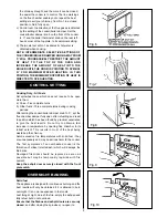
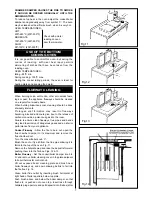
bolts (Fig. 8).

After completing the installation, the Heating Contractor should
demonstrate to the user, the operation of the appliance and the
routine cleaning method.

Check that the system is full of water and free from air locks.

When lighting pull the flue chamber damper open to maximum,
add paper and sticks with a small quantity of fuel through
fuelling aperture onto bottomgrate and close the firebox door.

Open ashpit door, ignite fuel and close ashpit door when fuel is
well alight with boiler thermostat knob or spinwheel on ashpit
door at required setting.

Allow the cooker to heat up gradually at first time lighting.

NOTE: SMOKE/SMELL EMITTED DURING INITIAL USAGE

Some parts of the cooker have been coated with a light
covering of protective oil. During initial operation of the cooker,
this may cause smoke/smell to be emitted and is normal and
not a fault with the appliance, it is therefore advisable to open
doors and or windows to allow for ventilation. Lift the lids to
prevent staining the linings.

6

TESTING AND COMMISSIONING

INSTALLATION

DESN 510454 A

Fig.8

Summary of Contents for 355m

Page 1: ...se note that some original pages may not appear in original numerical order but have been rearranged for clarity or deleted if not appropriate WARNING This information is a copy of an original archive therefore Aga cannot be held responsible for its continued accuracy or relevance ...

Page 2: ...ating and domestic use normal setting for winter usage whilst manually operated spinwheel control on the front of the ashpit door will provide heat for cooking and domestic hot water normal setting for summer usage The cooker boiler flueway damper knob on the centre front of the cooker below the top plate requires to be set in conjunction with the flue chamber damper to obtain the appropriate serv...

Page 3: ...m the locking spindle and pull the door open To close the doors Gently push the door shut until the door catch makes contact with the locking spindle FIRE DOOR OPERATION SEE FIG 3 To open the door Lift the door by the handle and pull forward To close the door Lift the door up by the handle and push to shut THE FIREDOOR MUST BE LIFTED SLIGHTLY WHEN OPENING AND CLOSING OTHERWISE DAMAGE TO THE DOOR C...

Page 4: ...l supply of wood and paper on top of the bottomgrate bars together with a small quantity of fuel and light i Close and lock the ashpit door with the spinwheel control open j Close and lock the firedoor k With fire established open firebox door and fill firebox with fuel Check secondary air slide setting Fig 6 Close and lock firebox door Push flue chamber damper back to position which has been foun...

Page 5: ...uels Three complete turns during cooking periods After setting the cooker boiler damper knob to C set the flue chamber damper fully open after refuelling and reset to position which has been found by practical experience to give the best results Do not try to obtain a fast increase in temperature by opening flue chamber to its fullest extent This results in most of the heat being wasted up the chi...

Page 6: ...box and ashpit door are securely closed close the spinwheel tight and the flue chamber damper is set to No 1 Set the boiler thermostat knob to its minimum setting and the front damper knob to c Turn the flue dilution lever See Fig 7 from left to right hand so that the flue chamber door opens at the bottom and minimise burning rates NOTE THE PRECISE AMOUNT OF OPENING DEPENDS ON THE CHIMNEY DRAUGHT ...

Page 7: ...the grate when riddling and may even cause jamming Allow the fire to burn out and then open the ashpit door Lift off the clinker door See Fig 10 and insert hooked poker to drawn out any offending accumulation Replace clinker door after use The amount of clinker formation is dependent on the heating load or burning rate and should be checked weekly for any build up Excessive build up will lead to a...

Page 8: ...n monoxide a poisonous gas into the room Failure to ensure clean flueways flue pipes and bends may lead to emission of dangerous gases and an inferior performance from your appliance Cooker Flueway Allow the fire to burn out open the flue chamber damper to its maximum and remove the flue chamber door Turn the cooker boiler knob C Brush the soot or fly ash from the flue pipe allowing it to fall ont...

Page 9: ...vidual bar pulling forward to remove NOTE THERE ARE TWO TYPES OF BARS ASSEMBLED AND THE REPLACEMENT BARS SHOULD BE CHECKED AGAINST REPLACED BAR BEFORE REPLACEMENT The firebricks fitted to the Rayburn 355M are of first quality manufacture and providing the cooker has been installed and used correctly will have a reasonable life They are however expendable items and in time will require renewal Repl...

Page 10: ...ent parts if required are always available ex works Write to us should any difficulty be encountered in obtaining them from your usual supplier SMOKE SMELL EMITTED DURING INITIAL USAGE Some parts of the cooker have been coated with a light covering of protective oil During initial operation of the cooker this may cause smoke smell to be emitted and is normal and not a fault with the appliance it i...

Page 11: ...10 ...

Page 12: ...11 ...

Page 13: ...policy of continuous product improvement the Company reserves the right to change specifications and make modifications to the appliance described at any time Manufactured by Aga Station Road Ketley Telford Shropshire TF1 5AQ England www aga web co uk www agacookshop co uk www agalinks com ...

Page 14: ... are designed and constructed to meet the required safety standards when properly installed and used IMPORTANT NOTICE PLEASE READ THE ACCOMPANYING WARRANTY Any alteration that is not approved by Aga could invalidate the approval of the appliance operation of the warranty and could also affect your statutory rights Control of Substances Health and Safety Important This appliance may contain some of...

Page 15: ... boiler damper knob at C will produce 1 46kW 5 000 Btu h of hot water from the boiler Summer Use See para re Firebrick Positions With the cooker boiler damper knob at C and the oven maintained at roasting temperature the hot water output from the boiler will be 2 6kW 9 000 Btu h of hot water from the boiler Overnight banking with the cooker boiler damper knob at C will produce 1 46kW 5 000 Btu h o...

Page 16: ...ic lined and comply with BS 4543 The minimum diameter for a straight chimney is 175mm and if offsets are fitted the recommended minimum diameter is 200mm IN ALL TYPES OF CHIMNEYS THE MINIMUM HEIGHT FOR CORRECT OPERATION OF THE COOKER IS 5 5m AND SHOULD TERMINATE ABOVE THE ROOF IN ACCORDANCE WITH REGIONAL STATUTORY REQUIREMENTS RECOMMENDED FLUE DRAUGHT 2mm W G 0 08in MINIMUM THE APPLIANCE SHOULD BE...

Page 17: ...AIN PIPE ARE NOT RECOMMENDED BUT CERTAIN PROPRIETARY MAKES OF INSULATED CHIMNEY ARE SUITABLE Provision must be made for a permanent unobstructed air vent having a minimum effective area of 182 5cm2 28 25sq in communicated directly to outside air or an adjacent room which itself has a permanent air vent of at least the flue size direct to outside air Effect of Extractor Fan Avoid if possible the in...

Page 18: ...ation or maintenance The Rayburn 355M is delivered complete including a set of boiler removable firebricks where positional location determines the amount of hot water supplied in winter and summer seasons The oven side and firebox front firebricks are permanently fixed with fire cement whilst the two boiler face side bricks and boiler back brick are located for the summer season thereby providing...

Page 19: ...bottomgrate bars are in position Operate the riddling lever to ensure bottomgrate operation 4 Turn the boiler thermostat knob at the rear left hand corner of the top plate from No 1 low to No 8 high NOTE THE HIGHER THE NUMBER THE HIGHER THE WATER TEMPERATURE The handrail brackets are held on the front ends of the cooker top plate casting Remove the travel nuts and replace with the handrail bracket...

Page 20: ...7 ...

Page 21: ...olicy of continuous product improvement the Company reserves the right to change specifications and make modifications to the appliance described at any time Manufactured by Aga Station Road Ketley Telford Shropshire TF1 5AQ England www aga web co uk www agacookshop co uk www agalinks com ...

Reviews: