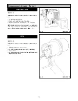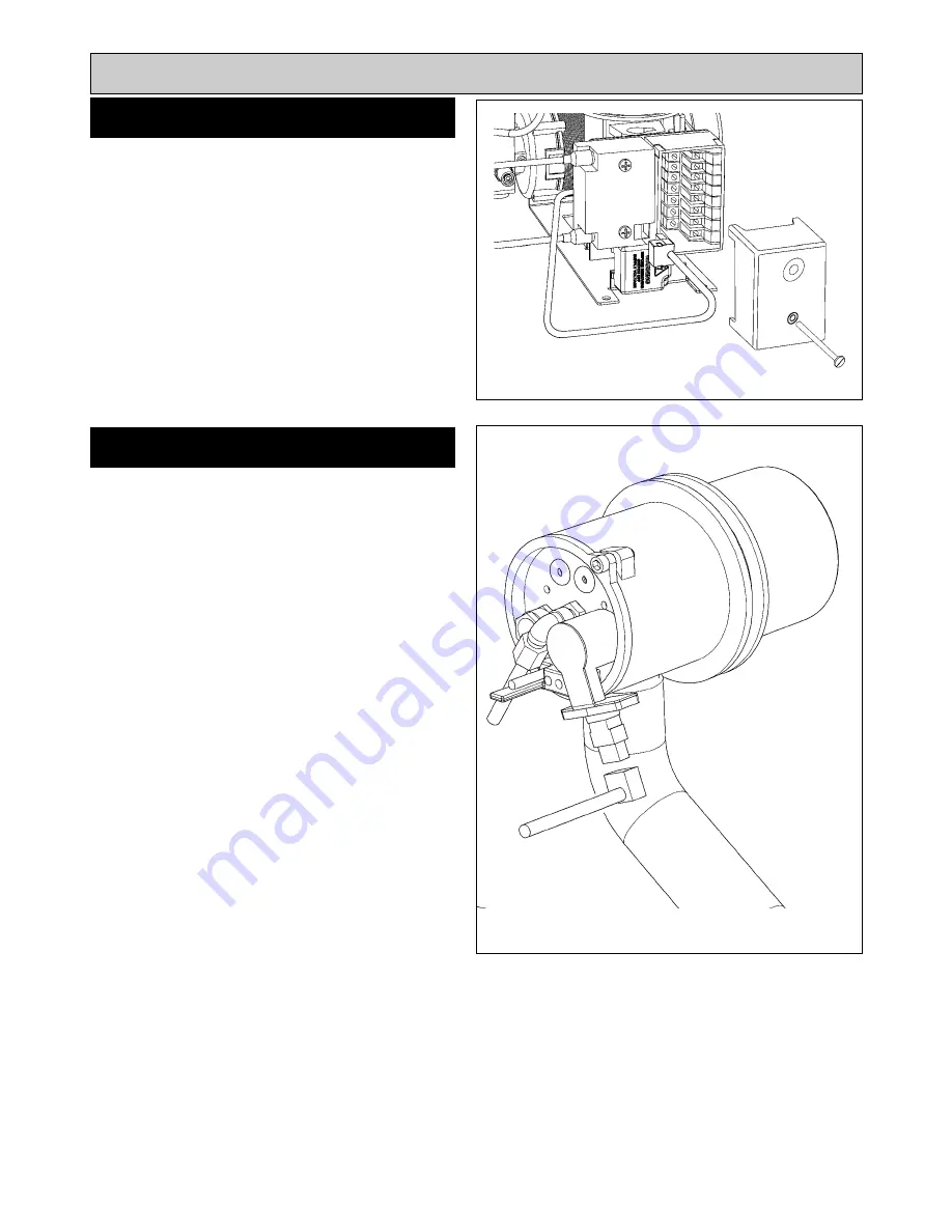
SEE FIG. 22
Follow instructions in section BURNER ACCESS, Steps 1
to 3.
1.
Undo centre fixing screw.
2.
Gently pull control box away from base.
3.
Fit new control box, re-assemble in reverse order.
NOTE:
Boiler burner must be removed from appliance in
order to gain access to control box. See instruction in
section burner removal, boiler burner, steps 1 to 4.
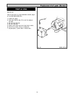
SEE FIG. 23
Follow instructions in section BURNER ACCESS, Steps 1
to 3.
1.
Withdraw PEC from burner head.
2.
Push in retaining clip and remove PEC from plug.
3.
Fit new PEC.
4.
Re-attach plug and re-insert PEC taking care to insert
the correct way round.
18
Replacement of parts (Burner)
PEC
CONTROL BOX
Fig. 22
Fig. 23
DESN 515772
DESN 515767
Summary of Contents for 660
Page 21: ...21 Fig 27 DESN 514774 Replacement of parts Electrical controls ...
Page 22: ...22 Fault Finding Fig 28 Rayburn 600 700 Wiring Diagram 111MB for Individual Satronic boxes ...
Page 23: ...23 Fault Finding Fig 29 Rayburn 600 700 Wiring Diagram 111MB self contained control ...
Page 29: ...Fault Finding 29 Fig 31A DESN 516838 ...
Page 30: ...30 Fault Finding ...
Page 31: ...31 Fault Finding ...
Page 33: ...33 ...
Page 34: ...34 ...
Page 35: ...35 ...


