pump is flushed out there may be some flame instability resulting in the burner locking out as indicated by the
signal light in the re-set button of the control box (
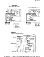
see fig 13
). In this event,
wait at least one minute, then press
the re-set button to re-start.
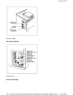
Fig. 14 BURNER OIL PUMP CONNECTIONS DESN 510229
Vent the Oil Pump (
see fig 14
)
Place a suitable container beneath the pump to collect the excess oil.
Slacken the bleed screw to release the trapped air in the pump. The burner will fire when the bleed screw is re-
tightened. (N.B. The burner may have locked out before all the air was released; repeat as often as necessary.
Check Oil Pressure (
see Fig. 14
)
Place a suitable container beneath the pump to collect the excess oil.
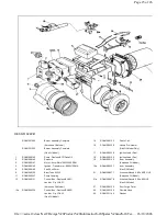
Unscrew and remove the bleed screw from the pump and fit an oil pressure gauge with R1/8 connection. Restore
the electricity supplies to the appliance. Switch on the burner and check the oil pressure on the pressure gauge. If
the pressure gauge is not indicating the correct reading then adjust the pressure by turning the pressure regulator
clockwise to increase, or anti-clockwise to decrease the pressure until the pressure gauge reads 10bar
(145Ibf/In
2
). Switch off the burner and disconnect all electrical supplies to the appliance. Remove the pressure
gauge and replace the bleed screw.
Check Combustion Air (
see fig 15
)
Switch on electricity supplies to the appliance. Switch on the burner and set cooker/burner damper control knob to
H (Heating). Remove the enamelled top plate cover panel (A) behind the LH insulating cover where a plugging
screw will be seen. Remove this screw and insert sensing end of portable indicator to check the CO
2
(carbon
dioxide). Adjust the burner air intake until 11.5% CO
2
of flue gases is recorded on the indicator.
Page 13 of 26
26/10/2006
file://\\server1\docs\NetCDs\Aga%20Product%20Information%20Spares%20and%20Tec...


