


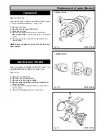
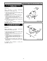
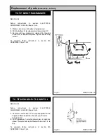
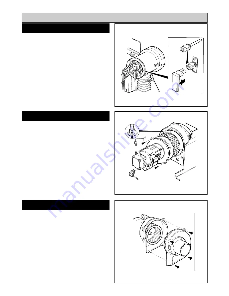
SEE FIG. 13
Withdraw Photo Electric Cell from the burner head. Clean
PEC sensing end with a soft cloth taking care not to
scratch the light sensitive body. Re-insert PEC taking care
to insert the correct way round.
Should the cell show signs of distortion or cracking,
replacement will be necessary. See PEC replacement,
page 19.
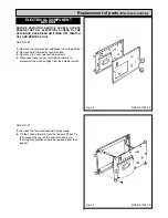
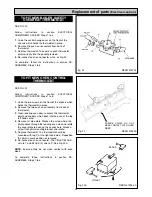
SEE FIG. 14 & 14A
440/460K ONLY
1.
Clean between the blades of the fan impellor with a
small brush and remove any residue.
The fan motor flange has 4 fixings to the fan case.
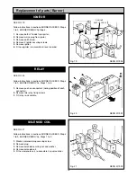
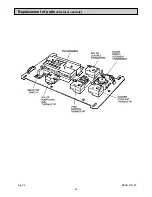
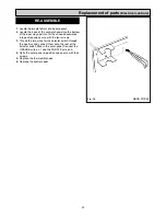
480/499K ONLY
1.
Remove 4 fixing screws and pull off fan can inlet.
2.
Clean between the blades of the fan impellor with a
small brush and remove any residue.
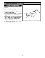
Re-assemble the burner in reverse order.
NOTE:
Burner head gaskets should be renewed at each
service.
13
Burner Servicing
FAN CLEANING
PHOTO ELECTRIC CELL (PEC)
CLEANING
RE-ASSEMBLE BURNER
Fig. 13
Fig. 14
DESN 512003
DESN 511996
440K & 460K
Fig. 14A
DESN 515883
480K & 499K
Summary of Contents for Heatranger 440
Page 9: ...Cleaning Fig 6A 9...
Page 22: ...22 Fig 28 DESN 513150 Replacement of parts Electrical controls...
Page 30: ...30 Electrical Controls CONTROL CIRCUIT BOILER Fig 37 L1...
Page 31: ...31 Electrical Controls CONTROL CIRCUIT COOKER Fig 38 L2 L2 KB MODEL ONLY...
Page 32: ...32 Fault Finding WIRING DIAGRAM APPLIANCE 440 460 480K 499K Fig 39...
Page 37: ...Fault Finding 37 Fig 41A DESN 516838...
Page 38: ...38 Fault Finding...
Page 39: ...39 Fault Finding...
Page 40: ...40 Fault Finding...
Page 41: ...41 Fault Finding...
Page 43: ...43...


