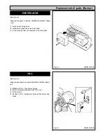
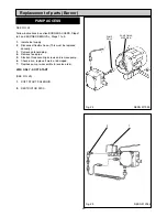
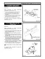
SEE FIG. 17A
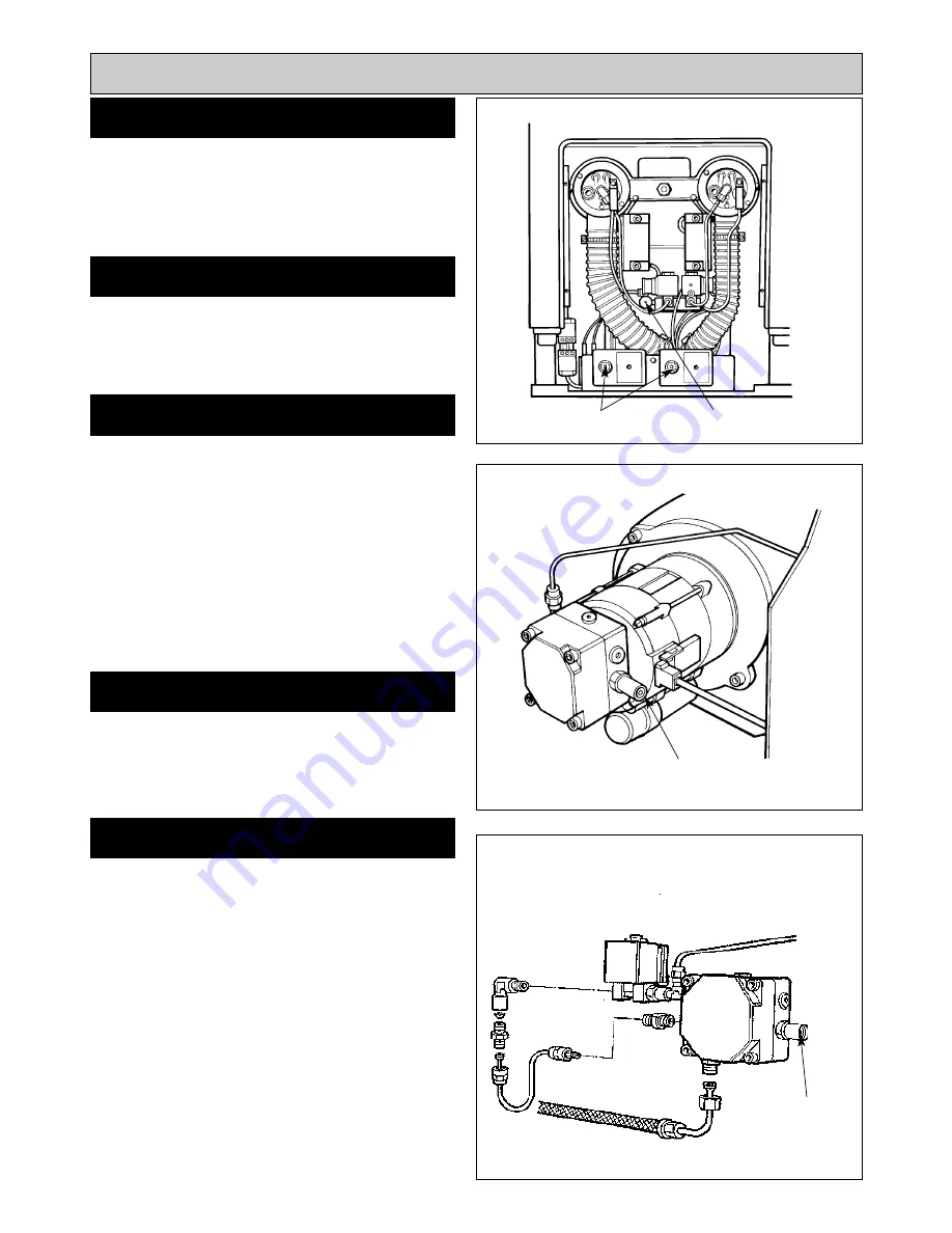
Disconnect the flexible oil pipe line at the pump inlet, open
the stop valve slowly and run off some of the oil into a
receptacle to establish an air free supply to the pump.
Remake the connection oil tight and leave valve open.
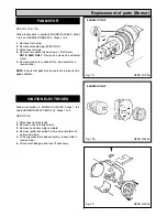
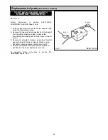
SEE FIG. 16
Remove the bleed screw from the manifold and fit an oil
pressure gauge with R 1/8 connection to check the pump
output pressure.
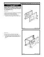
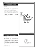
Set the boiler burner time clock to continuous and turn the
boiler thermostat to maximum. The boiler burner should
run on pre-purge for 7 - 15 seconds. With the ignition
spark energised. The oil solenoid valve should open
allowing the burner to fire.
Until all the air from the oil pump is flushed out there may
be some flame instability resulting in the burner locking
out. This will be shown by the burner stopping and the
illumination of the signal light in the reset button of the
control box (see Fig. 17).
IN THIS EVENT, WAIT AT
LEAST ONE MINUTE
, then press the re-set button to
restart.
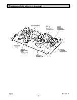
SEE FIG. 16
Whilst the burner is running, vent air from the pump by
slackening the pressure gauge port sufficient to allow air
to bleed out. When bubble free oil seeps out re-tighten.
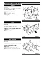
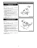
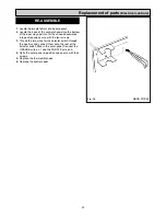
SEE FIG. 17
With the burner running check the oil pressure on the
pressure gauge.
If the pressure gauge is not indicating the correct reading
then adjust the pressure by turning the pressure regulator
clockwise to increase or anti-clockwise to decrease the
pressure until the pressure gauge reads 10 bar
(145Ibf/In
2
).
NOTE: 440K ONLY
Increase/decrease pressure until pressure gauge reads 8
bar (120Ibf/In
2
).
NOTE: 499K ONLY
During initial start up, the pressure will indicate
approximately 100 psi for 30 seconds then up to 10 bar
(145Ibf/In). Any adjustments must be made after this
sequence has been completed.
15
BLEED AIR FROM OIL SUPPLY
FIT PRESSURE GAUGE
SWITCH ON ELECTRICITY
VENT OIL PUMP
ADJUST OIL PRESSURE
Re-commissioning
Fig. 16
Fig. 17
Fig. 17A
DESN 511999
DESN 511997
DESN 512046
PRESSURE PORT/
BLEED SCREW
RESET
BUTTONS
OIL
PRESSURE
ADJUSTMENT
OIL
PRESSURE
ADJUSTMENT
Summary of Contents for Heatranger 440
Page 9: ...Cleaning Fig 6A 9...
Page 22: ...22 Fig 28 DESN 513150 Replacement of parts Electrical controls...
Page 30: ...30 Electrical Controls CONTROL CIRCUIT BOILER Fig 37 L1...
Page 31: ...31 Electrical Controls CONTROL CIRCUIT COOKER Fig 38 L2 L2 KB MODEL ONLY...
Page 32: ...32 Fault Finding WIRING DIAGRAM APPLIANCE 440 460 480K 499K Fig 39...
Page 37: ...Fault Finding 37 Fig 41A DESN 516838...
Page 38: ...38 Fault Finding...
Page 39: ...39 Fault Finding...
Page 40: ...40 Fault Finding...
Page 41: ...41 Fault Finding...
Page 43: ...43...