


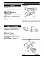
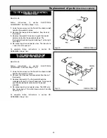
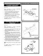
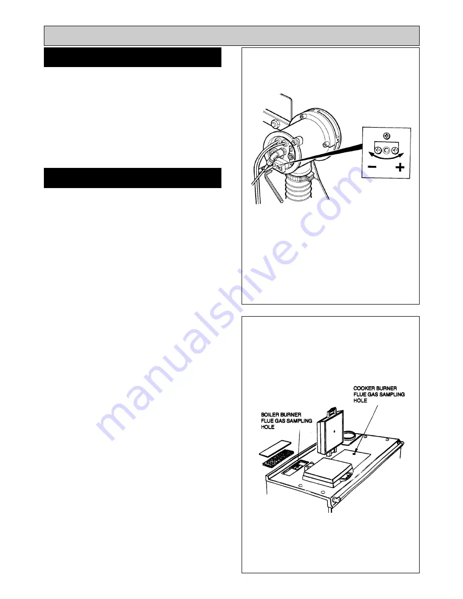
SEE FIG. 18 & 18A
After 15 minutes of the boiler burner running.
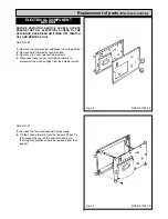
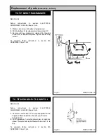
Remove the enamelled top cover panel and the insulation
pad.
Remove the plugging screw and insert the sensing end of
a portable indicator to check the CO
2
(Carbon Dioxide)
level. Adjust the boiler burner air intake until a reading of
11.0/11.5% is recorded on the indicator.
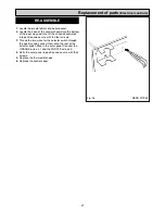
SEE FIG. 18A
Remove the CO
2
sampling tube and using the same hole
for flue sampling insert the sensing end of a Baccarach
Smoke Pump and check that the smoke in the boiler flue
ways does not exceed No. 2 on the scale.
Replace the plugging screw, insulation pad and cover
panel.
Switch off the boiler burner.
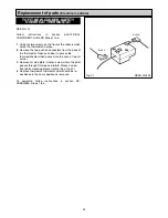
COOKER BURNER - SEE FIG. 18A
Switch on cooker burner.
After 15 minutes of the cooker burner running.
Repeat the above procedures for the cooker burner. To
sample the flue gases from the cooker burner lift up the
R.H. insulating cover and remove the countersunk
headed screw in the hotplate. The cooker burner should
be set to 11.0/11.5% maximum Smoke No. 2.
Replace the countersunk headed screw on completion
ensuring that it will not interfere with any pots and pans
placed on the hotplate.
16
SET COMBUSTION AIR
CHECK SMOKE
Re-commissioning
Fig. 18A
Fig. 18
DESN 511588
DESN 512001
Summary of Contents for Heatranger 440
Page 9: ...Cleaning Fig 6A 9...
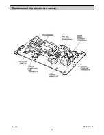
Page 22: ...22 Fig 28 DESN 513150 Replacement of parts Electrical controls...
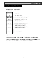
Page 30: ...30 Electrical Controls CONTROL CIRCUIT BOILER Fig 37 L1...
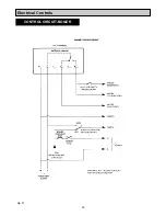
Page 31: ...31 Electrical Controls CONTROL CIRCUIT COOKER Fig 38 L2 L2 KB MODEL ONLY...
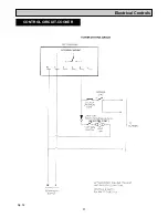
Page 32: ...32 Fault Finding WIRING DIAGRAM APPLIANCE 440 460 480K 499K Fig 39...
Page 37: ...Fault Finding 37 Fig 41A DESN 516838...
Page 38: ...38 Fault Finding...
Page 39: ...39 Fault Finding...
Page 40: ...40 Fault Finding...
Page 41: ...41 Fault Finding...
Page 43: ...43...


