


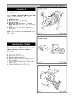
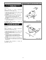
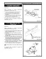
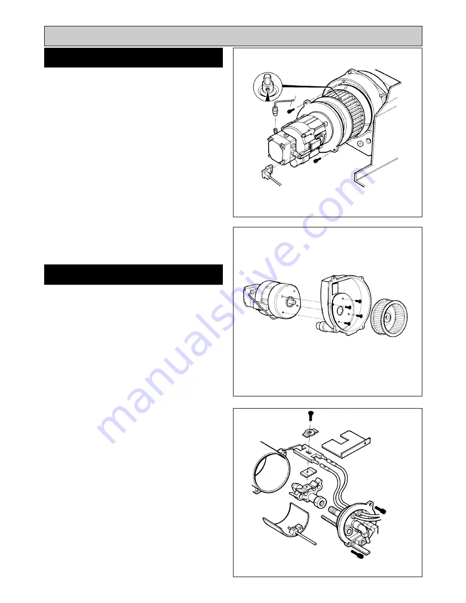
SEE FIG. 19 & 19A
Follow instructions in sections BURNER ACCESS, Steps
1 to 3 and BURNER REMOVAL, Steps 1 to 6.
1.
Remove 3-pin plug.
2.
Remove solenoid plug (499K ONLY).
3.
Disconnect oil pipe.
4.
Remove four socket head screws. Lift off motor.
NOTE: 440K ONLY -
Remove 4 screws and withdraw
motor.
5.
Remove grub screw, slide off fan. Re-assemble in
reverse order.
NOTE:
Ensure that gaskets and seals are in place and in
good condition.
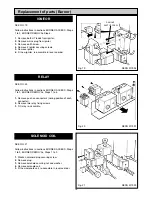
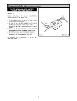
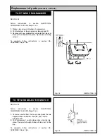
Follow instructions in BURNER ACCESS, Steps 1 to 3
and BURNER NOZZLE REMOVAL, Steps 1 to 5.
SEE FIG. 20
1.
Disconnect ignition leads.
2.
Remove 2 socket head screws.
3.
Remove head assembly complete.
4.
Remove ignitor assembly by removing countersunk
screw and clamp.
5.
Fit new ignition electrode assembly, re-assemble in
reverse order.
6.
Check electrode gap and reset if necessary.
17
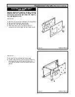
FAN MOTOR
Fig. 19
DESN 511996
Fig. 20
DESN 512004
IGNITION ELECTRODES
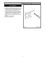
Replacement of parts (Burner)
Fig. 19A
DESN 515884
440/460K ONLY
480/499K ONLY
Summary of Contents for Heatranger 440
Page 9: ...Cleaning Fig 6A 9...
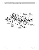
Page 22: ...22 Fig 28 DESN 513150 Replacement of parts Electrical controls...
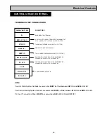
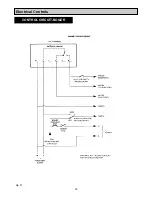
Page 30: ...30 Electrical Controls CONTROL CIRCUIT BOILER Fig 37 L1...
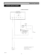
Page 31: ...31 Electrical Controls CONTROL CIRCUIT COOKER Fig 38 L2 L2 KB MODEL ONLY...
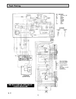
Page 32: ...32 Fault Finding WIRING DIAGRAM APPLIANCE 440 460 480K 499K Fig 39...
Page 37: ...Fault Finding 37 Fig 41A DESN 516838...
Page 38: ...38 Fault Finding...
Page 39: ...39 Fault Finding...
Page 40: ...40 Fault Finding...
Page 41: ...41 Fault Finding...
Page 43: ...43...


