


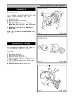
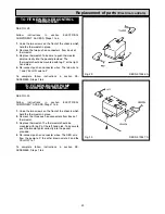
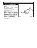
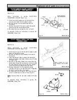
SEE FIG. 19
Follow instructions in sections BURNER ACCESS, Steps
1 to 3, BURNER REMOVAL Step 4.
1.
Remove both HT leads from ignitor,
2.
Remove mains plug from ignitor.
3.
Remove earth screw.
4.
Remove 2 ignitor securing screws.
5.
Remove ignitor.
6.
Fit new ignitor, re-assemble in reverse order.
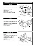
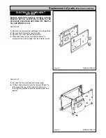
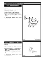
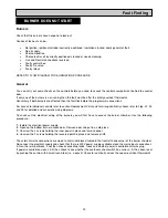
SEE FIG. 20
Follow instructions in sections BURNER ACCESS, Steps
1 to 3, BURNER REMOVAL, Steps 1 to 6.
1.
Remove push on connectors (noting position of each
connector).
2.
Remove two relay fixing screws.
3.
Fit relay, re-assemble.
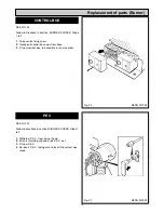
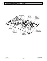
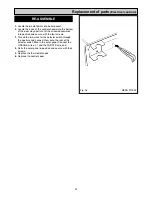
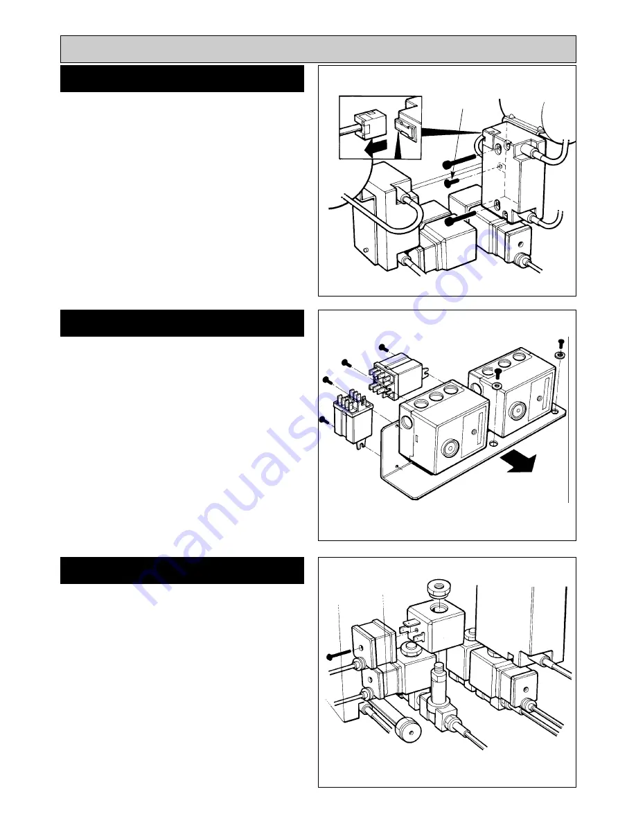
SEE FIG. 21
Follow instructions in sections BURNER ACCESS, Steps
1 to 3, BURNER REMOVAL, Steps 1 to 5 .
1.
Slacken solenoid plug securing screw.
2.
Remove plug.
3.
Remove solenoid securing nut and washer.
4.
Remove solenoid coil.
5.
Fit new solenoid coil, re-assemble in reverse order.
18
Replacement of parts (Burner)
Fig. 19
DESN 511994
Fig. 20
DESN 511991
Fig. 21
DESN 511993
RELAY
SOLENOID COIL
IGNITOR
REMOVE
EARTH SCREW
Summary of Contents for Heatranger 440
Page 9: ...Cleaning Fig 6A 9...
Page 22: ...22 Fig 28 DESN 513150 Replacement of parts Electrical controls...
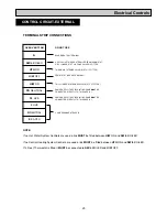
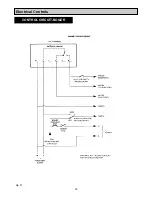
Page 30: ...30 Electrical Controls CONTROL CIRCUIT BOILER Fig 37 L1...
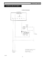
Page 31: ...31 Electrical Controls CONTROL CIRCUIT COOKER Fig 38 L2 L2 KB MODEL ONLY...
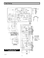
Page 32: ...32 Fault Finding WIRING DIAGRAM APPLIANCE 440 460 480K 499K Fig 39...
Page 37: ...Fault Finding 37 Fig 41A DESN 516838...
Page 38: ...38 Fault Finding...
Page 39: ...39 Fault Finding...
Page 40: ...40 Fault Finding...
Page 41: ...41 Fault Finding...
Page 43: ...43...


