


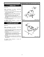
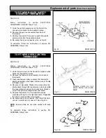
SEE FIG. 31
Follow instructions in section ELECTRICAL
COMPONENT ACCESS, Steps 1 to 6.
1.
Undo the two screws on the front of the chassis which
holds the thermostat in place.
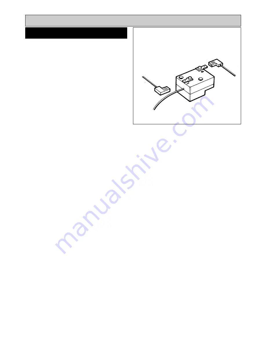
2.
Remove the two push on connectors from the back of
the thermostat. Open oven door to access the
thermostat phial which passes into the oven at top LH
corner.
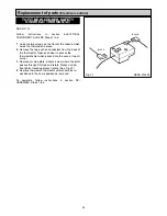
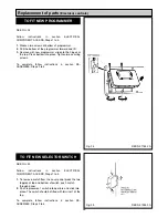
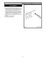
3.
Remove LH side plate, slacken screw where the phial
passes through RH side and rotate. Slacken screw
front phial mounting bracket rotate. (See Fig. 33).
4.
Replace thermostat, thermostat phial should be re-
positioned in the same position as removed.
To complete, follow instructions in section RE-
ASSEMBLE, Steps 1 to 6.
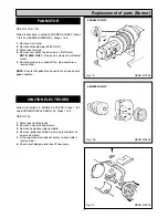
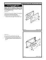
TO FIT NEW COOKER SAFETY
OVERHEAT THERMOSTAT
Fig. 31
DESN 512493
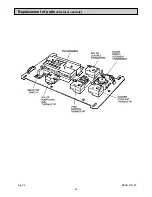
Replacement of parts
(Electrical controls)
24
BLACK
BLACK
Summary of Contents for Heatranger 440
Page 9: ...Cleaning Fig 6A 9...
Page 22: ...22 Fig 28 DESN 513150 Replacement of parts Electrical controls...
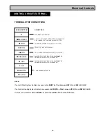
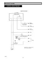
Page 30: ...30 Electrical Controls CONTROL CIRCUIT BOILER Fig 37 L1...
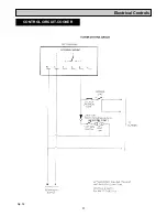
Page 31: ...31 Electrical Controls CONTROL CIRCUIT COOKER Fig 38 L2 L2 KB MODEL ONLY...
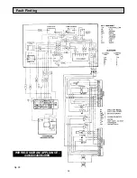
Page 32: ...32 Fault Finding WIRING DIAGRAM APPLIANCE 440 460 480K 499K Fig 39...
Page 37: ...Fault Finding 37 Fig 41A DESN 516838...
Page 38: ...38 Fault Finding...
Page 39: ...39 Fault Finding...
Page 40: ...40 Fault Finding...
Page 41: ...41 Fault Finding...
Page 43: ...43...


