


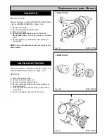
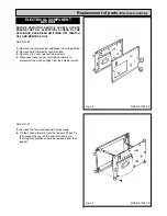
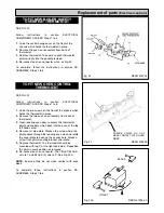
1.
Locate thermostat phials into boiler pocket.
2.
Locate the base of the control chassis into the bottom
of the door way aperture, tilt the chassis backwards
into position and secure with the four screws.
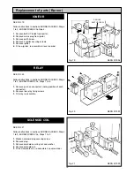
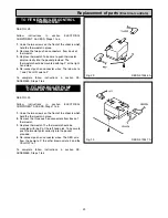
3.
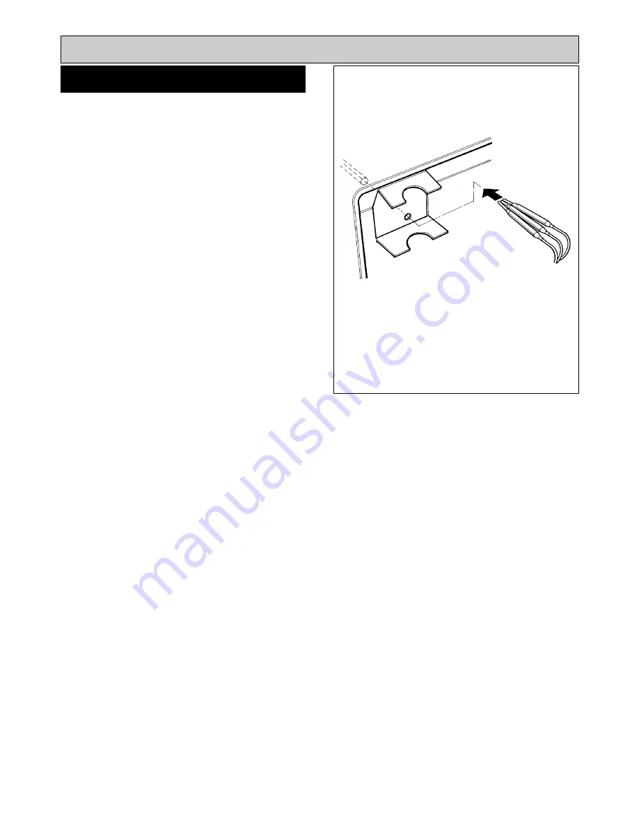
Thread the two wires for the selector switch through
the aperture and connect them onto the rear of the
selector switch fitted in the outer panel. Connect the
ORANGE wire on 1 and the PURPLE wire on 2.
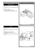
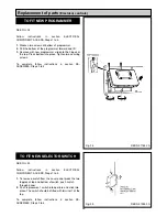
4.
Refix the outer panel in position and secure with the 2
screws.
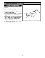
5.
Replace the thermostat knobs.
6.
Replace the controls door.
27
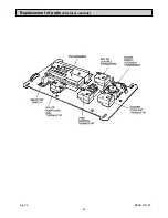
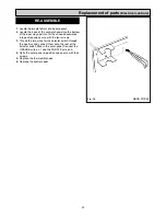
Replacement of parts
(Electrical controls)
RE-ASSEMBLE
Fig. 36
DESN 511989
Summary of Contents for Heatranger 440
Page 9: ...Cleaning Fig 6A 9...
Page 22: ...22 Fig 28 DESN 513150 Replacement of parts Electrical controls...
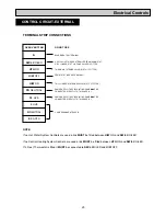
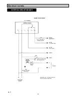
Page 30: ...30 Electrical Controls CONTROL CIRCUIT BOILER Fig 37 L1...
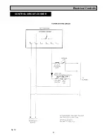
Page 31: ...31 Electrical Controls CONTROL CIRCUIT COOKER Fig 38 L2 L2 KB MODEL ONLY...
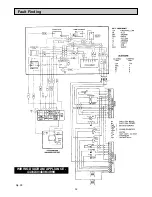
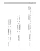
Page 32: ...32 Fault Finding WIRING DIAGRAM APPLIANCE 440 460 480K 499K Fig 39...
Page 37: ...Fault Finding 37 Fig 41A DESN 516838...
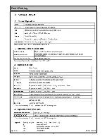
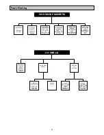
Page 38: ...38 Fault Finding...
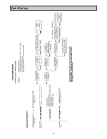
Page 39: ...39 Fault Finding...
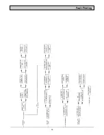
Page 40: ...40 Fault Finding...
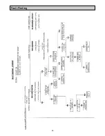
Page 41: ...41 Fault Finding...
Page 43: ...43...


