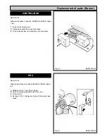
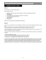
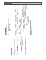


Burners
Check that the burners have not gone to lock-out.
Causes of lock-out can be:-
l
No ignition, ignition electrode incorrectly positioned, insulation cracked, spark generator fault.
l
No oil supply.
l
Poor combustion.
l
Photo electric cell incorrectly positioned, cracked or needs cleaning.
l
Live and Neutral connections reversed.
l
Faulty control box.
l
Faulty fire valve.
l
Faulty relays.
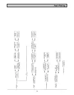
REFER TO FLOW DIAGRAM FOR ELIMINATION PROCEDURE.
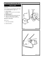
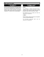
General
You can carry out some checks on the controls before you need to access the controls compartment behind the control
door.
If only one of the burners is not running then the fault must be after the safety overheat thermostat.
Conversely if both burners are affected then the fault lies before the programmer connections.
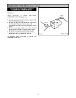
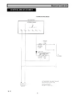
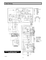
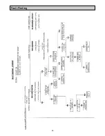
For access to individual controls refer to section Replacement Parts and for wiring continuity checks refer to Figs. 37, 38
and 39 for detailed and schematic wiring diagrams.
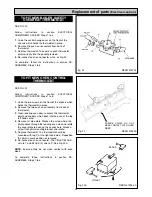
To check out the electrical wiring at the burners you will first have to access the burner chamber. Use the following
procedure:-
1.
Isolate the electrical power supply.
2.
Open up the bottom burner access door. Remove door and put in a safe place.
3.
Unscrew the 4 screws holding the inner panel in place and remove panel.
4.
Unscrew the 3 screws holding the louvered plinth in place and remove plinth.
The external mains connections are made to a terminal block situated in the front left-hand corner of the burner chamber.
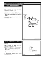
Re-connect the electrical supply and check that there is 230V power supply available cross the mains input connection L
& N on the terminal block, if not then check connecting leads, fuses and whether power is available at mains plug.
If power is available across L & N then check to see whether the overheat cut-out switch has cut-out., if it has been reset
by pushing the centre with a small round tool (i.e. a pencil). Check for continuity across the cooker overheat thermostat.
33
BURNER DOES NOT START
Fault Finding
Summary of Contents for Heatranger 440
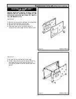
Page 9: ...Cleaning Fig 6A 9...
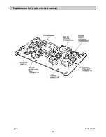
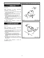
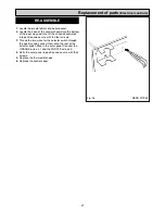
Page 22: ...22 Fig 28 DESN 513150 Replacement of parts Electrical controls...
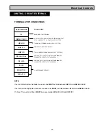
Page 30: ...30 Electrical Controls CONTROL CIRCUIT BOILER Fig 37 L1...
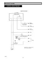
Page 31: ...31 Electrical Controls CONTROL CIRCUIT COOKER Fig 38 L2 L2 KB MODEL ONLY...
Page 32: ...32 Fault Finding WIRING DIAGRAM APPLIANCE 440 460 480K 499K Fig 39...
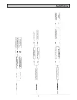
Page 37: ...Fault Finding 37 Fig 41A DESN 516838...
Page 38: ...38 Fault Finding...
Page 39: ...39 Fault Finding...
Page 40: ...40 Fault Finding...
Page 41: ...41 Fault Finding...
Page 43: ...43...


