
Fault Finding
36
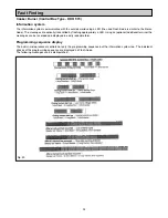
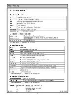
Cooker Burner (Control Box Type DKO 970N) - Information system
The information system is microprocessor based and reports on all aspects of burner control box operation and flame
supervision. It informs continuously about the actual programming sequence the unit is just performing. Besides monitoring
of the programming sequence it also allows to identify errors during start-up of operation without any additional testing
devices. The automatically performed diagnoses is a valuable tool which facilitates service/maintenance work and
therefore saves costs. The analyses of the error cause can be done directly on stage or if not possible afterwards at the
lockout reason is stored in a non-volatile lock out mode memory.
The information system communicates with the outside world using a LED (the used Flash-Code is similar to the Morse-
Code). The messages are optically transmitted by flashing apprioriately a LED. Using an (optional) additional terminal the
messages can be recorded and displayed in easy readable form.
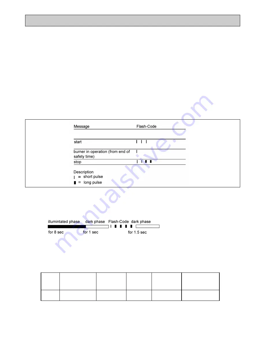
Programming sequence display
The built-in microprocessor controls not only the programming sequence but the information system too. The individual
phases of the programming sequence are displayed as Flash-Code.
The following messages can be distinguished:
Fig. 41
DESN 516837
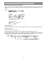
Lock-out diagnoses
In case of failure the LED is permanently illuminated. Every 10 seconds the illumination is interrupted by a flash code,
which indicates the cause of the error. Therefore the following sequence is performed which is repeated as long as the
unit is not reset.
Sequence:
Stray Light Monitoring
The stray light check is performed at the end of the pre-purge time for the duration as mentioned in the table of timings
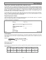
Blinking Codes: See Fig. 41A
Model
Pre-purge and
pre-ignition time
tv1
stray light
monitoring
tf
safety time
ts
post-ignition
time after v1
tn
delay time to V2
DKO 972-N-only
tv2
05
15
5
5
7
20
Table of timings (sec.)
Summary of Contents for Heatranger 440
Page 9: ...Cleaning Fig 6A 9...
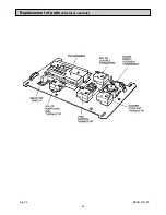
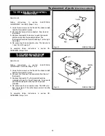
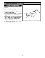
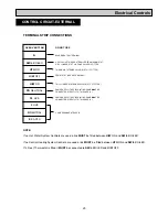
Page 22: ...22 Fig 28 DESN 513150 Replacement of parts Electrical controls...
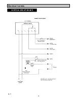
Page 30: ...30 Electrical Controls CONTROL CIRCUIT BOILER Fig 37 L1...
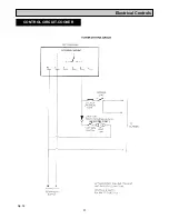
Page 31: ...31 Electrical Controls CONTROL CIRCUIT COOKER Fig 38 L2 L2 KB MODEL ONLY...
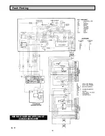
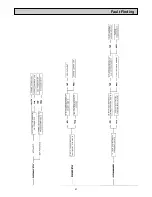
Page 32: ...32 Fault Finding WIRING DIAGRAM APPLIANCE 440 460 480K 499K Fig 39...
Page 37: ...Fault Finding 37 Fig 41A DESN 516838...
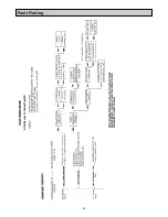
Page 38: ...38 Fault Finding...
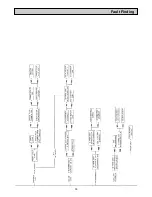
Page 39: ...39 Fault Finding...
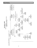
Page 40: ...40 Fault Finding...
Page 41: ...41 Fault Finding...
Page 43: ...43...