


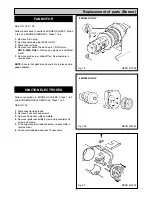
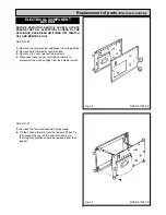
IMPORTANT: DURING BURNER REMOVAL CARE
MUST BE TAKEN NOT TO DAMAGE THE CERAMIC
FIBRE INSULATION.
SEE FIG. 2, 3 & 4
1.
Place a sheet on the floor in front of the cooker to act
as a working area.
2.
Disconnect the 4-pin plug at the side of the burner.
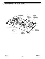
3.
Disconnect air intake.
SEE FIG. 3
4.
Undo the burner locking nut and remove head
retaining bar.
5
. Undo burner mounting nut.
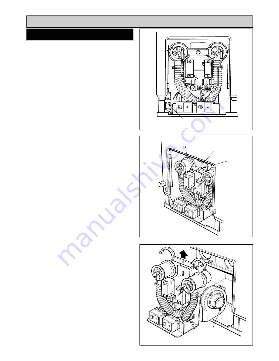
SEE FIG. 4
6.
Withdraw the burner unit.
7.
To remove the burner unit completely, it may be
necessary to disconnect the air intake hose from the
burner unit.
7
BURNER REMOVAL
Fig. 2
Fig. 3
Fig. 4
DESN 511999
DESN 512007
DESN 512006
Burner Removal
DISCONNECT 4-PIN PLUG
HEAD RETAINING
BRACKET
CENTRE LOCKING
NUT
DISCONNECT
AIR INTAKE
BURNER LOCKING
NUT
Summary of Contents for Heatranger 440
Page 9: ...Cleaning Fig 6A 9...
Page 22: ...22 Fig 28 DESN 513150 Replacement of parts Electrical controls...
Page 30: ...30 Electrical Controls CONTROL CIRCUIT BOILER Fig 37 L1...
Page 31: ...31 Electrical Controls CONTROL CIRCUIT COOKER Fig 38 L2 L2 KB MODEL ONLY...
Page 32: ...32 Fault Finding WIRING DIAGRAM APPLIANCE 440 460 480K 499K Fig 39...
Page 37: ...Fault Finding 37 Fig 41A DESN 516838...
Page 38: ...38 Fault Finding...
Page 39: ...39 Fault Finding...
Page 40: ...40 Fault Finding...
Page 41: ...41 Fault Finding...
Page 43: ...43...


