IMPORTANT: DURING CLEANING CARE MUST BE
TAKEN NOT TO DAMAGE THE CERAMIC FIBRE
INSULATION.
SEE FIG. 5
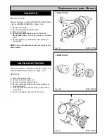
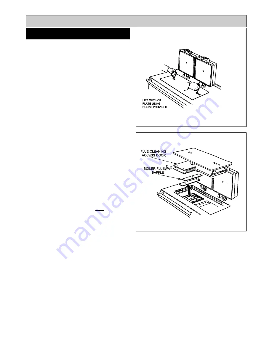
1.
Lift insulation covers and remove hotplate using lifting
hooks provided.
SEE FIG. 6
2.
Remove the 4 flue cleaning access door securing bolts
and remove door.
3.
Using the rods provided remove the boiler flueway
baffles from between boiler cross waterways.
The baffles are assembled in alternate directions, to allow
gases to flow front to back through the assembly.
Each heat exchanger has two rows of baffles
Ensure that the baffles are having the top and bottom
plates of the same width and marked
TOP
are fitted last.
One at top of each flueway.
Total number of baffles fitted are:-
440 = 6
(2 x 3)
460 = 6
(2 x 3)
480 = 8
(2 x 4)
499 = 10
(2 x 5)
8
HEAT EXCHANGER CLEANING
Cleaning
Fig. 5
Fig. 6
DESN 510523
DESN 512011
Summary of Contents for Heatranger 440
Page 9: ...Cleaning Fig 6A 9...
Page 22: ...22 Fig 28 DESN 513150 Replacement of parts Electrical controls...
Page 30: ...30 Electrical Controls CONTROL CIRCUIT BOILER Fig 37 L1...
Page 31: ...31 Electrical Controls CONTROL CIRCUIT COOKER Fig 38 L2 L2 KB MODEL ONLY...
Page 32: ...32 Fault Finding WIRING DIAGRAM APPLIANCE 440 460 480K 499K Fig 39...
Page 37: ...Fault Finding 37 Fig 41A DESN 516838...
Page 38: ...38 Fault Finding...
Page 39: ...39 Fault Finding...
Page 40: ...40 Fault Finding...
Page 41: ...41 Fault Finding...
Page 43: ...43...