background image

3

Boiler Water Connections
Flow (one)

Rp 1 (1in.BSP Int)

Return (one)

Rp 1 (1in.BSP Int)

Both connections are located towards the
rear edge of the appliance L.H. side panel.

Oil Inlet

10mm copper
To connect to the R.H. 
side panel.

Electrical Supply

230V ~ 50Hz 270 W
3 Amp Fused

Flue Outlet

125mm

CO

2

%

- BOILER

11.0/11.5

- COOKER

11.0/11.5

Max. Water Temp.

82°C

Water Capacity of

11.5  litres

Boiler

Weight of Appliance

395kg

Max. Operating 

2 bar (20m)

Pressure of Boiler

Fuel - Kerosene 

C2

GENERAL SPECIFICATIONS

ELECTRIC AND

OIL

CONNECTIONS

Summary of Contents for Heatranger 460K

Page 1: ...This information refers to the following products Rayburn 460K 480K 499K Open Flue MX models Fitted with Nu Way burners...

Page 2: ...WARNING This information is a copy of an original archive therefore Aga cannot be held responsible for its continued accuracy...

Page 3: ...11566 MX raywarranty aga rayburn co uk PLEASE READ THESE INSTRUCTIONS BEFORE INSTALLING THIS APPLIANCE For use in GB and IE Installation Instructions Heatranger 460 480 499K At the Heart of your Home...

Page 4: ...gloves face masks and eye protection After handling wash hands and other exposed parts When disposing of the product reduce dust with water spray ensure that parts are securely wrapped Kerosene and Ga...

Page 5: ...panel Oil Inlet 10mm copper To connect to the R H side panel Electrical Supply 230V 50Hz 270 W 3 Amp Fused Flue Outlet 125mm CO2 BOILER 11 0 11 5 COOKER 11 0 11 5 Max Water Temp 82 C Water Capacity of...

Page 6: ...ZZLE US g h 0 65 80 EH 0 40 80 EH 10 145 28 5 17 6 10 145 47 5 29 3 23 5 OIL PRESSURE Bar psi OIL BURNING RATE cc m HEAT INPUT kW BOILER OUTPUT kW 480K COOKER BURNER TOTAL OUTPUT kW 18 2 3 1 TOTAL OUT...

Page 7: ...andards Scotland Technical Standard Part F Heat producing appliances and storage of liquid and gaseous fuel Building Regulations Northern Ireland Technical Booklet to Part L Heat producing appliances...

Page 8: ...y at the point where the oil line enters the building The sensing bulb of the fire valve MUST be fitted to the clips located on the L H side of the appliance The 5 10 micron oil filter supplied with t...

Page 9: ...LENGTH METRES H METRES 10mm OD 12mm OD 0 35 30 25 20 15 8 6 100 100 100 90 70 30 20 0 5 1 0 1 5 2 0 2 5 3 0 REFER TO INSTRUCTION SHEET FOR DETAILS ON FITTING TWO PIPE SYSTEM GRAVITY SINGLE FEED PIPE S...

Page 10: ...ue gas temperatures a brick chimney should be fitted with a suitable multifuel stainless steel flexible liner Where it is necessary to avoid condensation such as an exposed end gable insulation such a...

Page 11: ...as to reduce the resistance to air flow 4 The ventilation requirement for kitchens in Part F of the Building Regulations is for mechanical extract at the rate of 60 litres per second or 30 litres per...

Page 12: ...ss the boiler at full output of 10 14 C When horizontal runs are used the pipes should rise upwards in the direction away from the appliance Circulating Pump It is recommended that the selected pump b...

Page 13: ...able room temperatures for economic operation and for control of the domestic hot water flow to the cylinder Consideration should be given to fitting a frost thermostat switch should be set to operate...

Page 14: ...nts 12 Typical External Wiring with Honeywell 3 Port Mid Position Valve For use with 460 480K Typical External Wiring with 2 Honeywell N C Motorised 2 Port Zone Valves For use with models 460 480 499K...

Page 15: ...e power cable is that it should be a 3 core PVC sheathed flexible cord 85 C min at least 0 75mm2 24 x 0 2mm to the relevant standard WARNING THIS APPLIANCE MUST BE EARTHED In the event of an electrica...

Page 16: ...14 Site requirements FIG 4 460 480 499 K...

Page 17: ...n air gap of 25mm between the wall and the rear of the cooker Fit the rear distance brackets as shown in Fig 5 Whenever possible it is recommended that the skirting board is removed for the width of t...

Page 18: ...overs and remove the hotplate using lifting hooks provided See Fig 7 5 Remove the 4 flue cleaning access door securing bolts and remove door 6 Check the position of the boiler flueway baffles 7 Replac...

Page 19: ...Installation requirements 17 FIG 8A...

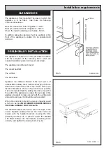
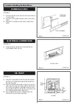
Page 20: ...met in the right hand side panel and locate in the clips provided 2 Before connecting the flexible oil pipe to the pump inlet open the stop valve slowly and run off some of the oil into a receptacle t...

Page 21: ...CYLINDER STAT ZONE VALVE S ETC IF FITTED PUMP SUPPLY THE CIRCULATING PUMP MUST BE CONNECTED DIRECTLY TO THIS SUPPLY PUMP SUPPLY THE CIRCULATING PUMP MUST BE CONNECTED DIRECTLY TO THIS SUPPLY 3 AMP PE...

Page 22: ...n allowing the burner to fire Until all the air from the oil pump is flushed out there may be some flame instability resulting in the burner locking out This will be shown by the burner stopping and t...

Page 23: ...and insert the sensing end of a portable indicator to check the CO2 Carbon Dioxide level Adjust the boiler burner air intake until a reading of 11 0 11 5 CO2 is recorded on the indicator Check Smoke...

Page 24: ...er When all air locks have been removed and the system is hot the by pass should be adjusted to ensure a quiet operation and the radiators balanced 4 Allow the pump adjuster to maintain a flow and ret...

Page 25: ...o mains water supply or to the water storage cistern supplying domestic hot water even though a non return valve may be fitted without the approval of the local water authority h The Filling Point The...

Page 26: ...24 Sealed System FIG 18...

Page 27: ...25...

Page 28: ...26...

Page 29: ...27...

Page 30: ...policy of continuous product improvement the Company reserves the right to change specifications and make modifications to the appliance described and illustrated at any time Manufactured By Aga Rayb...

Reviews: