


10
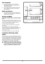
Gas connection
1.
Connect the gas supply to the 1/2” BSP tapered
thread on the left hand side of the appliance (See
“Specifications” page 3
).
2.
Test the whole of the gas installation including the
meter and purge in accordance with the relevant
recommendations.
Water connections
1.
The two flow and return (22mm O/D Copper Tube)
connections are located towards the rear edge of the
appliance left hand side panel.
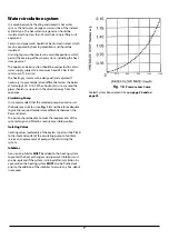
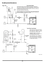
System suitability
THIS BOILER IS SUITABLE FOR FULLY PUMPED SYSTEMS
ONLY.
For optimum operating conditions the heating system into
which the boiler is installed, should include a control system.
Such a system will include a time switch and a room
thermostat and/or cylinder thermostat.
The boiler should be controlled so that it is operated on
demand only.
Operation of the system under control of the boiler
thermostat only does not produce the best efficiency. Refer
to the control equipment manufacturer’s literature for
information e.g. wiring.
The internal boiler/cooker wiring is shown in
Fig. 1.12
.
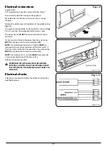
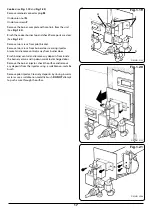
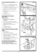
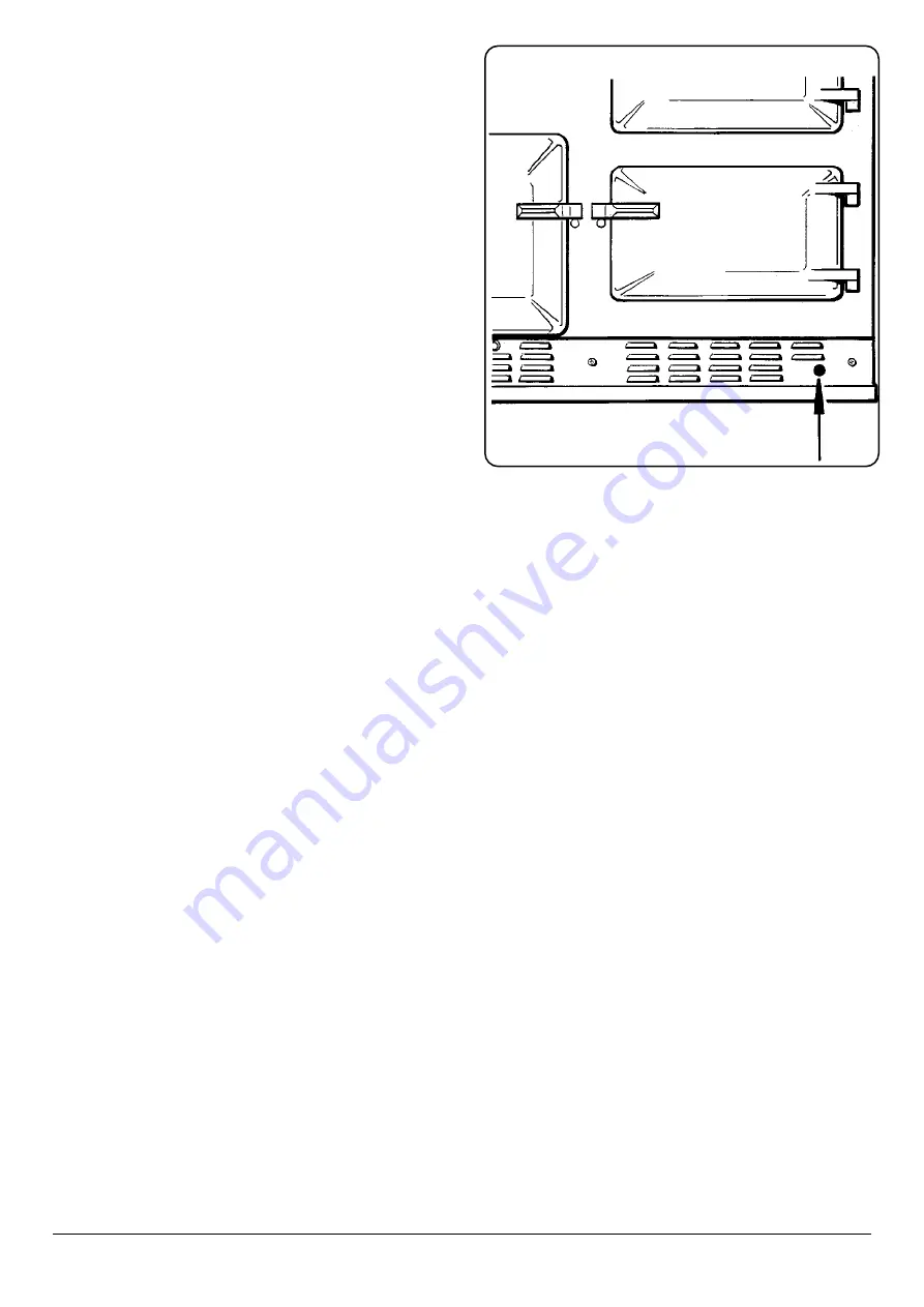
Combustion discharge safety
device
For safety purposes a combustion discharge safety device is
fitted. This will only operate under adverse flue conditions. If
the switch has operated, it should be pushed in to reset (
Fig.
1.8
). If this problem persists contact your local engineer to
determine and rectify the cause. It is important not to reset
more than once as this may indicate a flue blockage.
n
WARNING: The combustion discharge safety device
must not be interfered with or rendered inoperative,
as this could interfere with the safe operation of the
appliance and invalidate the appliance warranty.
Fig. 1.8
CDSD RESET BUTTON
DESN 511788


