


11
Electrical connections
Supply cable:
PVC insulated three core 85ºC rated 300/500V .75mm2.
To connect the electrical wiring to the appliance.
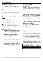
Make electrical connections to terminal strip as wiring
diagram.
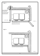
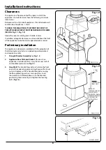
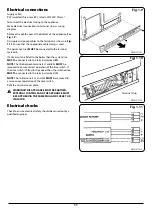
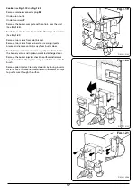
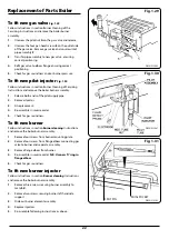
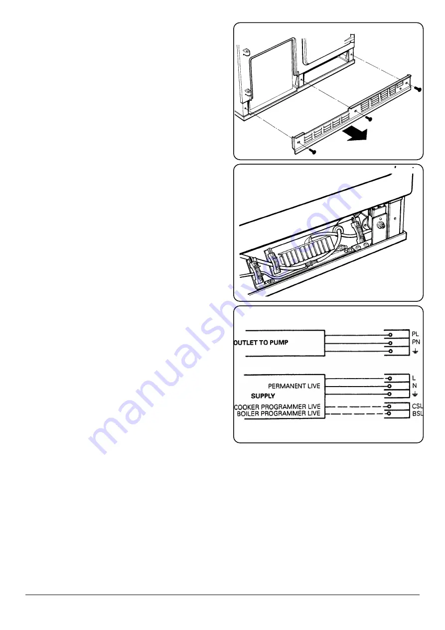
Remove the plinth cover at the bottom of the appliance (See
Fig. 1.9
).
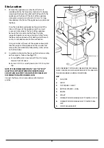
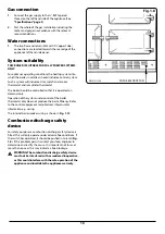
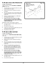
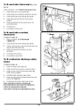
Fit supply and pump cables to the terminals as shown in
Fig.
1.11
. Ensure that the appropriate cable clamp is used.
The permanent live
MUST
be connected to the terminal
marked
L
.
If a time switch is fitted to the boiler then the system live
MUST
be connected to the terminal marked BSL.
NOTE
: The link between terminals L1 and BSL
MUST
be
removed to ensure correct operation of the time switch. If
the time switch is fitted to the cooker then the switched live
MUST
be connected to the terminal marked CSL.
NOTE
: The link terminals L1 and CSL
MUST
be removed to
ensure correct operation of the time switch.
Refit the terminal cover plate.
n
WARNING! THIS APPLIANCE MUST BE EARTHED,
EXTERNAL CONTROLS AND THE APPLIANCE MUST
BE SUPPLIED VIA THE SAME PLUG AND SOCKET OR
ISOLATOR.
Electrical checks
Check to ensure electrical safety should be carried out by a
qualified engineer.
Fig. 1.9
DESN 511767
DESN 511778
DESN 517924
Fig. 1.10
Fig. 1.11
Terminal Strip


