


14
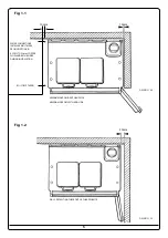
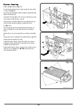
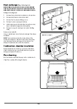
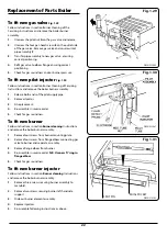
Main burner lighting see
Fig. 1.14
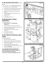
This appliance is fitted with a combustion discharge safety
device which will switch off both main burners in adverse
flue conditions. Before turning on main burners ensure that
the manual reset button, which is located on the right hand
side of the plinth is depressed (
Fig. 1.8
).
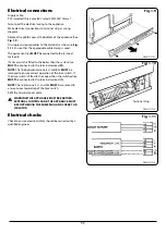
Ensure the electricity supply is turned ON and set any
external controls to the ON position.
Turn the boiler thermostat knob to MAX., and the boiler will
ignite.
Turn the cooker thermostat to H, and the cooker burner will
go to full rate.
Check for gas soundness of all leaks with leak detection fluid.
Turn off both burners.
Turn the thermostat knob to the required setting.
The boiler and pump should be run until the system is hot.
Check for water leaks, then flush the system with all manual/
automatic valves open. Upon refilling check the system for
leaks. When all the air has been removed from the water
circuit, the pump and radiators should be balanced to
achieve the correct temperature to drop across the system.
Set any timer room temperature, etc to suit the customer’s
requirements.
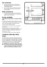
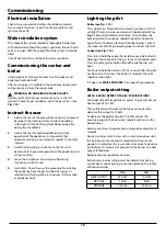
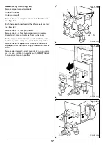
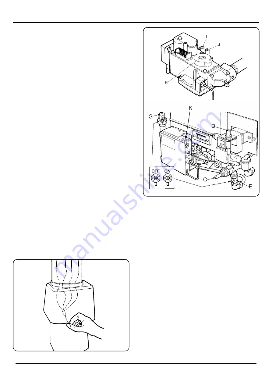
Spillage test
With cooker and boiler burners full on.
A spillage test must be carried out after 5 minutes, as follows:
Light a smoke match and position into the draught diverter
as shown in
Fig. 1.13
. If smoke does not spill back into the
room then the installation is satisfactory. If smoke is drawn
back into the room leave burners on for further 10 minutes
and check again.
n
WARNING: IF THE SMOKE SPILLS BACK INTO THE
ROOM, DISCONNECT THE APPLIANCE AND SEEK
EXPERT ADVICE.
Commissioning
DESN 517111
DESN 512964
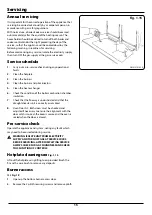
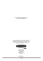
Fig. 1.14
Fig. 1.13
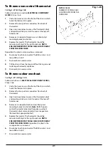
KEY
C - COOKER FLAME FAILURE OVERRIDE BUTTON
D - PIEZO IGNITION BUTTON - COOKER
E - GAS COCK - COOKER
G - GAS COCK - BOILER
H - BOILER BURNER PRESSURE REGULATOR ADJUSTMENT
SCREW
I - PRESSURE TEST NIPPLE INLET
J - PRESSURE TEST NIPPLE - BOILER BURNER
K - BOILER BURNER RESET
DESN 512965