background image

15

Annual servicing

It is important for the correct operation of the appliance that 

servicing be carried out annually by a competent person in 

accordance with gas safety regulations.
With normal use, a boiler/cooker service should be carried 

out immediately after the end of the heating season. The 

householder should be advised to turn off both boiler and 

cooker control knobs the night preceding the day of the 

service, so that the appliance will be cooled down by the 

following morning, in readiness for servicing.
Before commencing any service, isolate the electricity supply 

then turn OFF the gas supply at the gas service cocks.

Service schedule

1. 

Carry out a pre-service check noting any operational 

faults.

2. 

Clean the hotplate.

3. 

Clean the burners.

4. 

Clean the burner and pilot injectors.

5. 

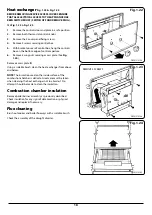
Clean the heat exchanger.

6. 

Check the condition of the boiler combustion chamber 

insulation.

7. 

Check that the flueway is unobstructed and that the 

draught diverter unit is correctly assembled.

8. 

Oven Door Fit - Both doors must be checked and 

adjusted if necessary to ensure the alignment with the 

door catch is correct, the keep is secure and the oven is 

sealed when the door is closed.

Pre-service check

Operate the appliance and system, noting any faults which 

may need to be corrected during service.


n

WARNING: ISOLATE UNIT FROM ELECTRICITY 

SUPPLY AND TURN OFF GAS AT SERVICE COCKS 

BEFORE SERVICING. AFTER COMPLETING SERVICE 

ALWAYS CHECK FOR GAS SOUNDNESS AND CHECK 

THIS FUNCTION OF CONTROLS.

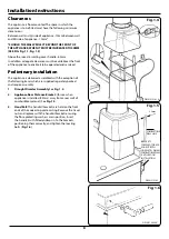
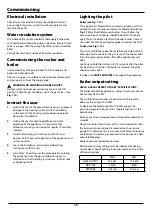
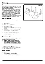
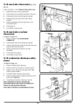
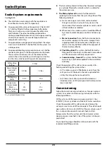
Hotplate cleaning see 

Fig. 1.15

Lift out the hotplate using lifting tools provided. Brush the 

fins with a wire brush to remove any deposits.
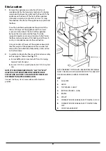
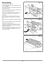
Burner access

SEE 

Fig. 1.9

1. 

Open up the bottom burner access door.

2. 

Remove the 3 plinth securing screws and remove plinth.

Servicing

DESN 510145 A

Fig. 1.15


Summary of Contents for Heatranger 480AG CF

Page 1: ...e mask and disposable gloves Glass Yarn Mineral Wool Insulation Pads Ceramic Fibre Kerosene Oil may be harmful if inhaled may be irritating to skin eyes nose and throat When handling avoid inhaling an...

Page 2: ...13 Main burner lighting 14 Spillage test 14 Servicing 15 Annual servicing 15 Service schedule 15 Pre service check 15 Hotplate cleaning 15 Burner access 15 Burner cleaning 16 Heat exchanger 18 Combust...

Page 3: ...rner pressure Min Boiler Output 17 6kW at 8mbar burner pressure 480AL PROPANE G31 TOTAL BOILER COOKER MIN MAX MIN MAX Max Heat Inputs Gross 35 8kW 40 7kW 25 6kW 30 5kW 10 2kW Max Heat Inputs Net 33 0k...

Page 4: ...ke and flame Where the cooker is to stand in a recess or against a wall which is to be tiled in no circumstances should the tiles overlap the cooker top plate NOTE SMOKE SMELL EMITTED DURING INITIAL U...

Page 5: ...LER MUST MAKE PROVISION TO GAIN ACCESS TO 22mm COPPER FLOW AND RETURN PIPE DURING INSTALLATION R 1 2 1 2 BSP TAPER 10mm 10mm 50mm MINIMUM GAP ON RIGHT HAND SIDE MINIMUM GAP ON LEFT HAND SIDE WALL PROJ...

Page 6: ...ipe constructed in a to c above should form the initial connection to lined chimneys Where a chimney is to be used which is not composed of or lined with a non porous acid resistant material it should...

Page 7: ...e pipes should rise upwards in the direction away from the appliance Circulating Pump It is recommended that the selected pump be sized to suit the boiler pressure loss see Fig 1 3 and therefore adequ...

Page 8: ...lowing items which are supplied separately packed and require assembly 1 Draught Diverter Assembly See Fig 1 4 2 Appliance Rear Distance Bracket for use when appliance is installed 25mm away from a re...

Page 9: ...take the weight of the appliance on the crowbar and remove the rear rolled tube followed by similar action on the front tube 2 Assemble and locate the flue draught diverter assembly on flue spigot as...

Page 10: ...ed so that it is operated on demand only Operation of the system under control of the boiler thermostat only does not produce the best efficiency Refer to the control equipment manufacturer s literatu...

Page 11: ...ive MUST be connected to the terminal marked BSL NOTE The link between terminals L1 and BSL MUST be removed to ensure correct operation of the time switch If the time switch is fitted to the cooker th...

Page 12: ...INK L1 TO CSL OR PROVIDE TIMED LIVE FOR COOKER BURNER LINK L1 TO BSL OR PROVIDE LIVE SUPPLY TO BOILER FROM PROGRAMMER OR AUXILIARY CONTROLS G Y G Y G Y G Y WH BL Y 9 8 7 3 G Y BR BR BL BR BR OR OR BL...

Page 13: ...ighting the pilot Boiler see Fig 1 14 This appliance is fitted with an automatic ignition unit that will light the main burner on demand Should button K see Fig 1 14 be illuminated press button this w...

Page 14: ...k the system for leaks When all the air has been removed from the water circuit the pump and radiators should be balanced to achieve the correct temperature to drop across the system Set any timer roo...

Page 15: ...rs 5 Clean the heat exchanger 6 Check the condition of the boiler combustion chamber insulation 7 Check that the flueway is unobstructed and that the draught diverter unit is correctly assembled 8 Ove...

Page 16: ...Fig 1 18 Brush the boiler burner top and check the flame ports are clear Any deposits may be removed with a non metallic brush Remove three screws securing burner assembly to manifold A Remove two sc...

Page 17: ...ing injector bracket and remove controls away from burner door Brush burner venturi and remove any deposits from inside the burner venturi and tip downwards to discharge debris Remove the burner injec...

Page 18: ...access plate See Fig 1 24 Remove access plate R Using a suitable brush clean the heat exchanger from above and below NOTE The insulation used on the inside surface of the combustion chamber is delica...

Page 19: ...ON Following the sequence in COMMISSIONING INSTRUCTIONS To fit new burner Follow instructions in section Burner Cleaning of Servicing Instructions and remove the cooker burner assembly 1 Remove two p...

Page 20: ...rmostat control knobs 3 Remove the 2 cover panel fixing screws 4 Remove cover panel SEE Fig 1 26 5 Remove the two control panel fixing screws 6 Tilt the chassis from the top and lift out taking care n...

Page 21: ...thermostat capillaries 9 Re assemble in reverse order To fit new cooker overheat See Fig 1 27 AND Fig 1 28 Follow instructions in ELECTRICAL COMPONENT ACCESS Steps 1 to 6 1 Undo the two screws on the...

Page 22: ...or 3 Fit replacement 4 Re assemble in reverse order 5 Check for gas soundness To fit new burner Follow instructions in section Burner cleaning Instructions and remove the boiler burner assembly 1 Remo...

Page 23: ...spindle locknut and extract overheat thermostat 5 Fit replacement thermostat 6 Re assemble in reverse order To fit combustion discharge safety device SEE Fig 1 33 Fig 1 34 1 Remove CDSD phial from sp...

Page 24: ...er or return side of all heat emitters or radiators b Where access to a make up vessel would be difficult by a remote automatic pressurisation and make up unit c Mains Connection There shall be no con...

Page 25: ...LTERNATIVELY THE BYPASS LOOP CAN INCORPORATE A TOWEL RAIL CONTROLLED BY A NON ADJUSTABLE BALANCING VALVE SHOULD THE PUMP BE FITTED TO THE RETURN THEN THE PRESSURE GAUGE AND EXPANSION VESSEL ARE FITTED...

Page 26: ...change specifications and make modifications to the appliances described and illustrated at any time www agaliving com www agacookshop co uk Manufactured By AGA Rangemaster Station Road Ketley Telfor...

Reviews: