


4
Location
The appliance must be installed on a solid level floor or base
of incombustible material which is capable of supporting the
total weight.
The location chosen for the appliance must permit
installation and the provision of a satisfactory flue and an
adequate air supply. The location must also provide space for
servicing and air circulation around the appliance.
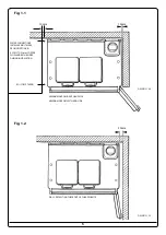
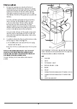
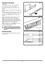
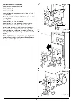
Between wall and LH side of appliance
10mm Between
wall and RH side of appliance
10mm*
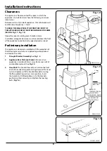
*SHOULD THE WALL PROJECT BEYOND THE FRONT OF
THE APPLIANCE, WHEN IT MUST BE INCREASED TO 50MM
(SEE FIG. Fig. 1.1, Fig. 1.2).*
Above the raised insulating cover handle 60mm
NOTE: GAS AND WATER CONNECTIONS ARE LOCATED
ON THE LH SIDE OF THE APPLIANCE. INSTALLERS MUST
MAKE PROVISION FOR ACCESS TO THESE CONNECTIONS
DURING INSTALLATION.
In addition, adequate clearance must be available at the
front of the appliance to enable it to be operated and
serviced. Flue pipes and fittings must not be closer than
25mm to combustible materials and where passing through
a combustible partition such as a ceiling or roof, must be
enclosed in a non-combustible sleeve providing an air space
of at least 25mm.
Spaces around flue pipes passing through walls or floors
should be sealed against the passage of smoke and flame.
Where the cooker is to stand in a recess or against a wall
which is to be tiled,
in no circumstances should the tiles
overlap the cooker top plate.
NOTE: SMOKE/SMELL EMITTED DURING INITIAL USAGE.
Some parts of the cooker have been coated with a light
covering of protective oil. During initial operation of the
cooker, this may cause smoke/smell to be emitted and is
normal and not a fault with the appliance, it is therefore
advisable to open doors and or windows to allow for
ventilation. Lift the insulating lids to prevent staining the
linings.
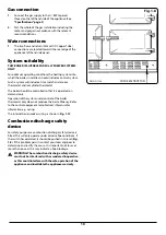
Gas supply
Pipework from the meter to the appliance must be of
adequate size. It is recommended that ø22mm minimum
diameter copper tubing is used. Do not use pipes of a smaller
size than the appliance gas connection. The complete
installation must be tested for soundness and purged in
accordance with the regulations in force.
Electrical supply
External wiring must be correctly earthed, polarised and
in accordance with current regulations. The main supply
required is 230V, 50Hz fused at 3A.
NOTE
: The method of connection to the electricity supply
must facilitate complete electrical isolation of the appliance,
preferably by the use of a fused three pin plug and
unswitched shuttered outlet. Alternatively, connection may
be made by a via a fused double-pole isolator with a contact
separation of at least 3mm in all poles and serving the
appliance and system control only.
Site Requirements


