


9
Site Location
1.
Remove the appliance assembly from the transit
wooden pallet by the temporary location of a sloping
ramp board between the pallet and the floor. With the
appliance on the floor, lift the front of the appliance
(manually or crowbar) and insert a 32mm x 1m long
tube between the front of the appliance base plate and
the floor.
Draw the tube balanced appliance forward until the
tube is at the rear of the appliance and then insert
a second similar tube at the front of the appliance,
between the base plate and the floor. The tube
supported appliance can now slowly be “rolled” across
the floor and positioned with its back against the wall,
and in its intended location for flue connection.
Using a crowbar at the rear of the appliance base plate,
take the weight of the appliance on the crowbar and
remove the rear rolled tube, followed by similar action
on the front tube.
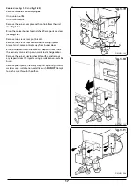
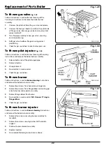
2.
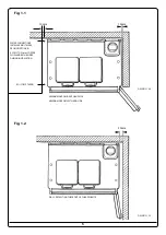
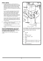
Assemble and locate the flue draught diverter assembly
on flue spigot as follows (See
Fig. 1.7
):-
a.
Ensure baffle plate is located with ‘front’ stamping
towards front of cooker.
b.
Ensure C.D.S.D. is correctly located in C.D.S.D. in phial
clip.
NOTE: IT IS RECOMMENDED THAT A “SLIP” OR “SPLIT”
ADAPTOR IS FITTED BETWEEN THE DIVERTER FLUE
SOCKET AND FLUE PIPE TO FACILITATE POSSIBLE FLUE
DISCONNECTION AFTER COMMISSION.
Connect the flue system in accordance with standard
practice.
Fig. 1.7
DESN 512141 A
1
2
6
9
3
5
4
8
7
NOTE: INCORRECT FITTING OF COMBUSTION DISCHARGE
SAFETY DEVICE COULD ALLOW PRODUCTS TO LEAK INTO
THE ROOM UNDER ADVERSE CONDITIONS.
KEY
1.
FLUE PIPE
2.
HOOD
3.
TOP SPACER - SHORT
4.
BOTTOM SPACERS - LONG
5.
BAFFLE
6.
SPIGOT
7.
COMBUSTION DISCHARGE SAFETY DEVICE (C.D.S.D.)
8.
COMBUSTION DISCHARGE SAFETY DEVICE PHIAL
CLIP
9.
CDSD PHIAL BRACKET


