background image

16

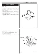
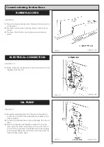
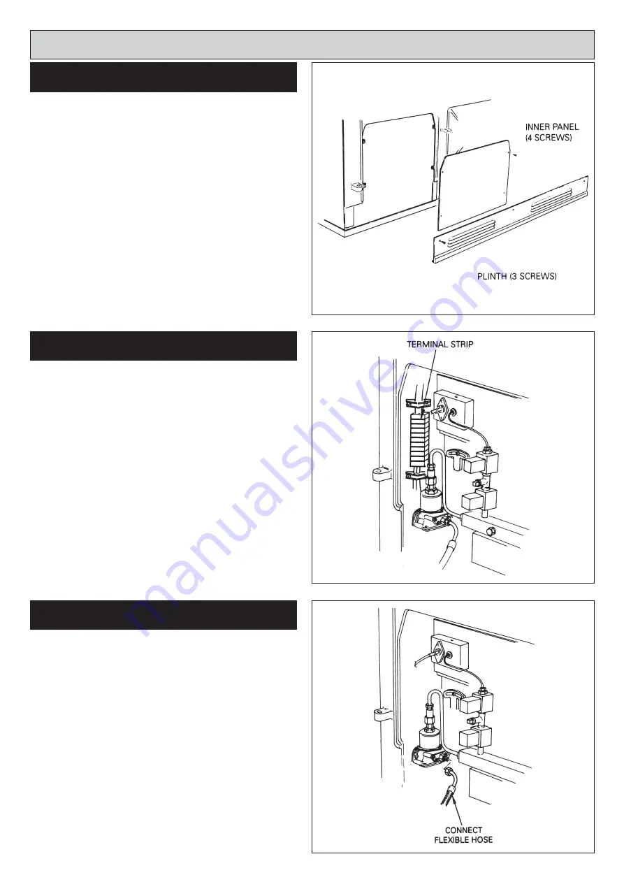
SEE FIG. 9.

1.

Open the burner access door. Remove door and put in
a safe place.

2.

Remove 4 inner panel securing screws and remove 
panel.

3

Remove the 3 plinth securing screws and remove 
plinth.

SEE FIG. 10

1.

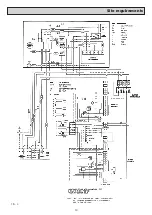
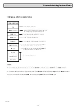
Make electrical connections to terminal strip as wiring
diagram (See Fig. 12)

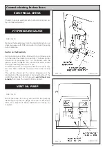
SEE FIG 11

1.

Bring the sensing phial of the fire valve through the 
grommet in the left hand side panel and locate in the 
clips provided.

2.

Connect the flexible hose to the outlet pipe from the oil
filter.

3.

Before connecting the flexible oil pipe to the pump 
inlet, open the stop valve slowly and run off some of 
the oil into a receptacle to establish an air free supply 
to the pump. Make the connection onto the pump oil 
tight and leave valve open.

Commissioning Instructions

FIG. 9

DESN 511124

DESN 511233

DESN 511234 

FIG. 10

FIG. 11

BURNER ACCESS

OIL PUMP

ELECTRICAL CONNECTION

Summary of Contents for Heatranger 480D

Page 1: ...WARNING This information is a copy of an original archive therefore Aga cannot be held responsible for its continued accuracy...

Page 2: ...O T H E R G B I E P A T E N T S P E N D I N G PLEASE READ THESE INSTRUCTIONS BEFORE INSTALLING THIS APPLIANCE For use in GB and IE Installation Instructions Heatranger 480D A At t t th he e H He ea ar...

Page 3: ...Glass Yarn Mineral Wool Insulation Pads Ceramic Fibre May be harmful if inhaled May be irritating to skin eyes nose and throat When handling avoid contact with skin or eyes Use disposable gloves face...

Page 4: ...nce L H side panel Oil Inlet R1 4 1 4 BSP Taper Ext Electrical Supply 230V 50Hz 3 amp Fused Flue Outlet 150mm CO2 BOILER 11 5 COOKER 11 0 Max Water Temp 82 C Water Capacity of 25 5 litres Boiler Weigh...

Page 5: ...5 29 3 23 5 OIL PRESSURE Bar psi OIL BURNING RATE cc m HEAT INPUT kW BOILER OUTPUT kW 480K COOKER BURNER BOILER BURNER BURNER NOZZLE US g h 0 40 80 SF 9 0 130 17 6 0 8 MAX 9 0 130 29 3 23 5 OIL PRESS...

Page 6: ...ngland Wales Part J Heat producing appliances Building Standards Scotland Technical Standard Part F Heat producing appliances and storage of liquid and gaseous fuel Building Regulations Northern Irela...

Page 7: ...torage tank to the appliance must be fitted with a remote acting fire valve operating at 150 F fitted with an appropriate length of capillary to enable the valve body to be located externally at the p...

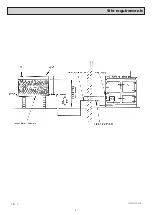
Page 8: ...Site requirements 7 DESN 510519 FIG 1...

Page 9: ...iance must not be less than the equivalent area of 150mm diameter flue pipe and be at least 4 5m high The flue pipe must not be less than 150mm internal diameter Flue pipes and fittings between the ap...

Page 10: ...uld be positioned in the vertical plane to reduce the risk of blockage Ducts should be sized so as to reduce resistance to air flow 4 The ventilation requirement for kitchens in Part F of the Building...

Page 11: ...bject to a maximum head of 18 25m The heating system must be designed and adjusted if necessary to give a temperature differential across the boiler at full output of 10 14 C When horizontal runs are...

Page 12: ...tion with the hot water channel gives priority to either the domestic hot water or the supply of hot water for central heating DHW if external controls are fitted It is recommended that independent te...

Page 13: ...The installation should be protected by a 30mA Residual Current Circuit Breaker RCCB The minimum requirement for the power cable is that it should be a 3 core PVC sheathed flexible cord 85 C min at l...

Page 14: ...13 Site requirements FIG 4...

Page 15: ...ust be an air gap of 25mm between the wall and the rear of the cooker Fit the rear distance brackets as shown in Fig 5 Whenever possible it is recommended that the skirting board is removed for the wi...

Page 16: ...inate the flue system in accordance with the regulations in force 4 Lift up the insulating covers and remove the hotplate using lifting hooks provided See Fig 7 5 Remove the insulation pad B 6 Remove...

Page 17: ...e valve through the grommet in the left hand side panel and locate in the clips provided 2 Connect the flexible hose to the outlet pipe from the oil filter 3 Before connecting the flexible oil pipe to...

Page 18: ...NDER STAT ZONE VALVE S ETC IF FITTED PUMP SUPPLY THE CIRCULATING PUMP MUST BE CONNECTED DIRECTLY TO THIS SUPPLY PUMP SUPPLY THE CIRCULATING PUMP MUST BE CONNECTED DIRECTLY TO THIS SUPPLY 3 AMP PERMANE...

Page 19: ...n open allowing the burner to fire Until all the air from the oil pump is flushed out there may be some flame instability resulting in the burner locking out This will be shown by the burner stopping...

Page 20: ...w and insert the sensing end of a portable indicator to check the CO2 Carbon Dioxide level Adjust the boiler burner air intake until a reading of 11 5 CO2 is recorded on the indicator Check Smoke Remo...

Page 21: ...ing the water flow rate through individual heat emitters to ensure a satisfactory water temperature at each emitter 5 When the water system reaches working temperature check that the boiler thermostat...

Page 22: ...ed from a service pipe under mains pressure provided that this pressure is acceptable to the local water authority See Fig 20 SEALED SYSTEM REQUIREMENTS Air or Nitrogen charge pressure bar Pre Pressur...

Page 23: ...Sealed Systems 22...

Page 24: ...23...

Page 25: ...24...

Reviews: