background image

35

OIL STORAGE TANKS

Oil storage tanks made of steel and all connecting equipment 

(eg: filling pipes and vent pipes) should comply with B.S. 

799 Part 5. Galvanised steel must not be used. Polyethylene 

(Plastic) tanks should comply with OFTEC standard OFS T100 

and or equivalent. Oil should never be stored in translucent 

plastic containers.
An isolating valve should be fitted at the tank outlet, in an 

accessible position so that the oil supply to the appliance can 

be shut off if required. This isolating valve must be of a type 

suitable for use with oil. (See 

Fig. 9.3

Fig. 9.4

Fig. 9.5

 & 

Fig. 

9.6

).

In order to enable the sediment and water to be removed 

from tanks a drain valve should be fitted. Oil storage tank 

support must be carried out in accordance with the tank 

manufactures recommendations. Tanks should be located 

in the most un-obstructive position possible having taken 

safety, filling, maintenance and the need, if any, to provide a 

head of oil for the burner into consideration.

FUELS

THE RECOMMENDED FUEL IS KEROSENE 28 SECOND 

VISCOSITY FUEL OIL. 

FUEL SUPPLY LINE 

The oil supply line from the oil storage tank to the appliance 

should be of an approved and suitable pipe with a minimum 

internal diameter of 9mm (3/8”) and connected to the oil inlet 

connection located at the cooker left hand side.
Oil supply pipes are normally run in annealed copper tube 

complying to B.S. E.N. 1057. It can be obtained in coil or half 

hard form for use with bending machines. This pipe can 

also be obtained with protective plastic sheathing applied. 

Fittings for copper pipe should be compression of the 

flared manipulative type to B.S. 864: Part 2 1983. Steel pipes 

complying with B.S. 1387: 1985, if used, must be protected 

from corrosion. Galvanised pipe and fittings must not be 

used.
Screwed joints must only be made with tapered threads 

complying with B.S. 1740: Part 1: 1971.
Jointing materials must be of types intended for use with oil 

fuel. Special petroleum – resisting compounds and PTFE tape 

are suitable. External pipes should preferably be run with a 

continuous rise towards the direction of flow, so that one can 

be vented off. It is important to avoid high points which could 

cause air locks.
Exposed lengths of oil supply pipe must be properly 

supported by purpose made clips securely fixed in place. 

Metal clips formed so as to hold the pipe on to a saddle 

are preferred. Consideration should be given to avoiding 

routes which expose the pipe to severe chilling which could 

cause freezing of the oil. Where pipes are buried, they must 

be protected from accidental damage. The use of joints 

underground should be avoided if at all possible. If joints 

have to be fitted in pipes laid below ground, access to them 

must be provided. 
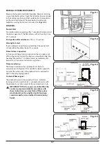
An oil filter (5 - 10 micron) and stop valve must be fitted 

to the fuel feed line and located near the supply tank and 

facilities should be provided to enable it to be serviced 

without draining down the oil supply system. (See 

Fig. 9.3

Fig. 9.4

Fig. 9.5

 & 

Fig. 9.6

).

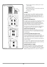
At the point where the oil line enters the building, the oil 

line must be fitted with an approved 65ºC remote acting 

fire valve, which meets the requirements of B.S. 5410: Part 1, 

fitted with the appropriate length of capillary. The heat sensor 

phial of the fire valve must be fitted to the clip provided in 

the burner compartment. It is absolutely essential that the 

fire valve is located externally and is as close as possible to 

the appliance. For existing installations where the oil supply 

are built into the structure internally, the remote acting 

fire valve should be fitted where the oil supply line is first 

exposed internally. This type of layout is not recommended 

for new installations.
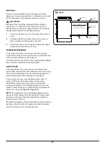
When gravity feed is used (the most common) the minimum 

head should not be below 1 meter (3’3”) and the maximum 

head should not exceed 6.5 meters (21’ 3”).

NOTE

: The pump is factory set for a single pipe installation 

to convert to a two pipe system consult manufacturer’s 

instructions.
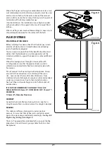
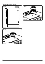
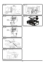
Before connecting the oil supply, secure appliance burner oil 

pipes to the base using the T junction (see 

Fig. 9.1

 & 

Fig. 9.2

).

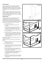
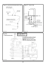
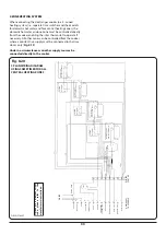
SINGLE PIPE SUPPLY SYSTEM: BOTTOM OF OIL STORAGE 

TANK ABOVE BURNER (See 

Fig. 9.3

)

Single pipe supply system: Tanks servicing this appliance by 

means of a single pipe need to be positioned so that they will 

apply the minimum head required 1 meter (3’ 3”) of oil to the 

burner when the fuel level is at its lowest point.
Refer to B.S. 5410 to calculate the additional head 

requirement relating to pipe length and size.

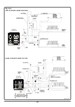
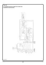
TWO PIPE SUPPLY SYSTEM: BOTTOM OF OIL STORAGE 

TANK BELOW OR LEVEL WITH BURNER (see 

Fig. 9.4

)

If the tank base is below the level at which the gravity feed to 

the burner can be maintained, a two pipe oil supply system 

may be adopted. (See 

Fig. 9.4

). The non-return valve in the 

supply line of the two pipe system is required to prevent oil 

running back from the burner and unpriming the oil pump. 

The non-return valve in the return line is only required if the 

top of the tank is above the burner. Its purpose is to prevent 

oil running back through the burner during maintenance.

SINGLE PIPE SYSTEM: WITH DE-AERATION DEVICE 

BOTTOM OF OIL STORAGE TANK BELOW OR LEVEL WITH 

BURNER. (see 

Fig. 9.5

):

This system can be used where the tank base is below the 

level at which gravity feed to the burner can be maintained 

and the burner incorporates an oil pump. The chamber is 

9.  Fuel Installation

Summary of Contents for Heatranger 60K

Page 1: ...tion Instructions CAUTION THIS UNIT IS HEAVY PROPER EQUIPMENT AND ADEQUATE MANPOWER MUST BE USED IN MOVING THE RANGE TO AVOID DAMAGE TO THE UNIT OR THE FLOOR REMEMBER when replacing a part on this app...

Page 2: ...o make a note of your Rayburn appliance Serial Number when it is being installed The serial number can be found on the rear of the appliance My Rayburn Details Serial No Rayburn Service No Dealer or s...

Page 3: ...RAMMING CENTRAL HEATING HOT WATER OR OVEN PREHEAT 6 SETTING THE ALARM TIMER 7 BOOST FUNCTION 7 ADVANCE FUNCTION IN AUTO MODE ONLY 7 DISPLAY LOCK FUNCTION 7 POWER FAILURE 8 HOTPLATE COOKING MODE 8 HOTP...

Page 4: ...AT 26 WATER CIRCUIT TEMPERATURE 26 CARE FOR YOUR CENTRAL HEATING SYSTEM 26 INDIRECT DOMESTIC CYLINDER 26 SERVICING 27 GENERAL MAINTENANCE 27 SAFETY VALVE 27 4 ZONE HEATING SYSTEM 33 9 Fuel Installatio...

Page 5: ...iance must be installed with an appropriate device that will allow permanent disconnection of the Live and Neutral conductors During Installation or disconnection prior to any electrical work the appl...

Page 6: ...ing up the burning pan to carry outside Deep Fat Frying Use a deep pan large enough to completely cover the appropriate heating area DO NOT hang dish towels on the handrail Doing so will restrict the...

Page 7: ...Regulations B S 5449 Forced circulation hot water central heating systems for domestic installations Health and Safety at Work Act B S 7671 Requirements for Electrical Regulations Safety Document 635...

Page 8: ...ility for Central Heating and Hot Water functions Alarm Timer allowing timing of cooking Built in battery to prevent loss of programmes during power cuts Diagnostics GENERAL NOTE ON SETTING THE PROGRA...

Page 9: ...o the normal mode after 60 seconds OPERATING THE OVEN MANUALLY 1 Simply turn the oven temperature control until the temperature desired appears on the LCD screen If oven ON and OFF times are shown can...

Page 10: ...ntire week The days you wish to program for can be changed by moving the flashing arrow using the and buttons Fig 4 4 shows the day setting for setting the same programme for Monday to Friday Fig 4 5...

Page 11: ...yed for 1 hour providing none of the oven control functions on the clock are used within this hour Boost can be cancelled by pressing the relevant function button Fig 4 8 ADVANCE FUNCTION IN AUTO MODE...

Page 12: ...e F button it will require the high limit switches to be reset to access and reset the high limit switches take the following steps 1 Remove plinth at base of cooker the high limit switches are locate...

Page 13: ...wire brush to keep the cast iron hotplate clean DO NOT USE ABRASIVE PADS OR OVEN CLEANERS CONTAINING CITRIC ACID ON ENAMELLED SURFACES ENSURE THAT THE CLEANSER MANUFACTURERS INSTRUCTIONS ARE ADHERED T...

Page 14: ...his method of oven grilling most of the fats are drawn out into the roasting tin Certain foods with little fat benefit from pan frying dry frying using a ribbed frying or griddle pan The foods cooked...

Page 15: ...use will be suitable There is a bakeware on the market of Continental design which has a steel base ideal for quickly absorbing the heat It is covered with a magnum enamel like coating which is safe t...

Page 16: ...s over WELL DONE 30 mins 30 mins over VEAL BONED AND ROLLED TOPSIDE SHOULDER FILLET 180oC MED 20 mins 20 mins over WELL DONE 25 mins 25 mins over VENISON ON THE BONE HAUNCH LEG SADDLE 180oC RARE 12 mi...

Page 17: ...ftened onion place the finely chopped onion and a little butter or oil in a heatproof bowl on or near the hotplate to soften I use this method often because it is so much easier than having to wash up...

Page 18: ...radiators Turn off un needed radiators f Radiator valves not balanced Adjust valves to give an even flow g By pass incorrectly set Adjust by pass valve 8 Domestic Hot Water Cylinder not getting hot e...

Page 19: ...icable that these appliances are so designed and constructed as to meet the general safety requirements when properly used and installed Section 10 of the Consumer Protection Act 1987 Safety Health an...

Page 20: ...y of the appliance should be increased overall by 10 mm beyond the figures quoted above This allows safe margin to take into account the natural dimensional variations found in major castings in parti...

Page 21: ...EIGHT 385Kg 850 lbs 80K BOILER OUTPUTS 23 45kW 80 000 Btu s Hr RADIATOR SURFACE 42 5 m2 457 ft 2 heating surface only 37 2 m2 400 ft 2 heating surface and domestic hot water FLUE GAS FLOW Boiler 0 004...

Page 22: ...Gal Hr Cycling N A N A N A 0 12 All data are taken under laboratory conditions and may vary in use Differential Pressure Across the Boiler Design flow rate through the boiler 38 2 L min 8 4 Gpm Stati...

Page 23: ...Safety at Work Act BS 7671 Requirements for Electrical Regulations Safety Document 635 The Electricity at Work Regulations BS 7593 Treatment of Water in Domestic Hot Water Systems BS 7074 Part 1 2 Hot...

Page 24: ...tection SI 1994 No 1768 plug and sockets etc safety Regulations 1994 Always install in accordance with current local wiring regulations You should always when either exposing or working with wiring co...

Page 25: ...with a sliding door ensure that the pipe continues up and is ultimately connected to the flue liner and well sealed with fire cement Do not connect to a flue serving another appliance Always ensure t...

Page 26: ...22 Fig 8 6 Fig 8 7 Fig 8 5 Flue greater than 125mm 5 Diameter DESN 517986 DESN 517987 DESN 517988...

Page 27: ...es that have proved to be unsatisfactory particularly with regard to down draught must not be considered for this appliance until they have been examined and any faults corrected If there is any doubt...

Page 28: ...tside walls should be sealed to prevent the ingress of moisture Existing air vents should be of the correct size and unobstructed for the appliance in use 10 If there is an air extraction fan fitted i...

Page 29: ...me control etc are operating satisfactorily and are compatible with the requirements of the cooker d Are any modifications necessary to make the heating system more efficient e Cleanse the system and...

Page 30: ...it board control panel is located within the appliance beneath the warming oven See Fig 8 1 WATER CIRCUIT TEMPERATURE The return water temperature should be maintained at not less than 50 C 122 F so a...

Page 31: ...son such as a plumber or heating engineer SAFETY VALVE A non adjustable 3 bar safety valve must be fitted to the primary flow pipe adjacent to the boiler connection ensuring that any discharge will no...

Page 32: ...28 RAYBURN HEATRANGER RAYBURN HEATRANGER Fig 8 13 RAYBURN HEATRANGER PRV PRV OPEN SYSTEM WITH PUMP ON RETURN SEALED SYSTEM WITH PUMP ON FLOW RAYBURN HEATRANGER DESN 517995...

Page 33: ...29 Fig 8 14 RAYBURN HEATRANGER RAYBURN HEATRANGER DESN 517997 DESN 517996...

Page 34: ...NT FUSED LIVE PUMP C 2 3 1 2 1 2 4 5 6 7 8 9 10 11 12 13 3 It is essential that the interstat can bring on the motorised valves directly as shown failure to observe this will result in nuisance lockou...

Page 35: ...31 If wires are a different colour code please refer to the manufacturers instructions Fig 8 18 WIRING DIAGRAM 100 80 60 DESN 518001...

Page 36: ...HEATING ZONES Note It is essential that the interstat can bring on one of the motorised valves directly as shown failure to observe this will result in nuisance lockout Please Note EARTHS NOT SHOWN FO...

Page 37: ...directly to the cooker EARTH EARTH POST MAINS NEUTRAL LIVE FLUE FAN INTERSTAT PUMP L PUMP N NEUTRAL HEATING Timer DHW Timer NO DHW Timer Boiler Run Heatranger TERMINALS WIRING CENTRE PERMANENT FUSED...

Page 38: ...TH POST MAINS Heatranger TERMINALS WIRING CENTRE NEUTRAL LIVE FLUE FAN INTERSTAT PUMP L PUMP N NEUTRAL HEATING Timer DHW Timer NO DHW Timer Boiler Run PERMANENT FUSED LIVE M Orange Grey Grey Brown Bro...

Page 39: ...ts underground should be avoided if at all possible If joints have to be fitted in pipes laid below ground access to them must be provided An oil filter 5 10 micron and stop valve must be fitted to th...

Page 40: ...done by turning off room thermostats time switches and temporarily linking terminals 6 9 This should bring on a motorised valve which will then call the boiler Note When the interstat calls normally t...

Page 41: ...burner as described under the heading Normal Start On flame failure immediately after burner start the control will initiate re ignition Flame monitoring The flame is monitored by a photocell unit No...

Page 42: ...9 6 Fig 9 7 Fig 9 8 Fig 9 9 Fig 9 10 Boiler Burner flue gas test point Oven Burner flue gas test point Fig 9 11 Fig 9 12 DESN 518010 DESN 518015 DESN 518016 DESN 518011 DESN 518011 DESN 518013 DESN 5...

Page 43: ...should not exceed 450mm 18 4 The chimney serving this appliance should not serve any other appliance 5 A suitable flue terminal should be fitted at the flue termination point 6 The flue should be cap...

Page 44: ...hange specifications and make modifications to the appliances described and illustrated at any time www agaliving com www agacookshop co uk Manufactured By AGA Rangemaster Station Road Ketley Telford...

Reviews: