INSTALLATION INSTRUCTIONS
SITE REQUIREMENTS
13
1
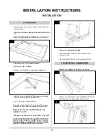
1. APPLIANCE LOCATION
2. VENTILATION
1.1 It is important that the cooker stands on a flat surface
capable of supporting the total weight of the cooker,
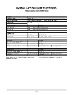
(See
Technical Specification page)
.
The cooker is supplied with a plinth adjustable in height
between 80 and 100mm. This plinth can also help to level
uneven floors.
1.2 Kitchen units can be fitted up to either side, allowing a
10mm gap between the kitchen surfaces and the cooker. If
a pine or similar wood surface is used, take care the wood
is well seasoned and protected from the side of the cooker
to prevent drying out or splitting.
1.3 Adequate clearance must be provided in front of the
appliance to allow it's complete removal from the location.
Certain serviceable components can only be changed by
removing the cooker from it's location and gaining access
to the rear of the appliance.
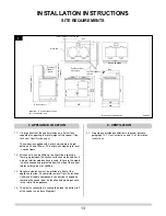
1.4 The electric connection is channelled along the bottom left
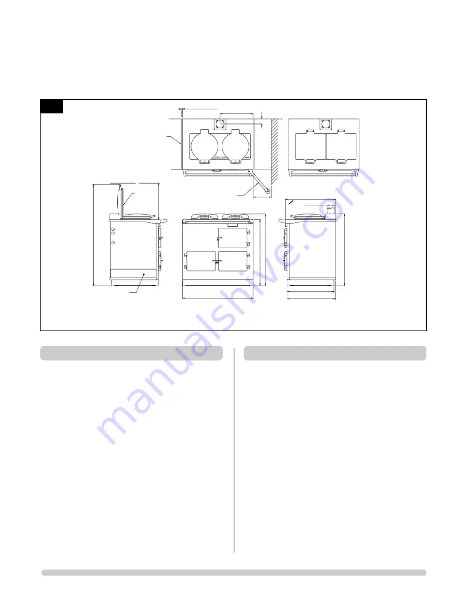
of the cooker, see above Diagram 1.
2.1 No purpose provided ventilation is required, but note
paragraph 12.1
User Instructions
and 1.1 of
Installation
Instructions.
Services duct
1393 Approximately
500mm minimum
clearance
Position of
lid when
raised
Position of door
when open
Square lid option
Dimensions in Millimetres
Work top
457
694
643
668
AR2008
976
988
986
908
10mm clearance to Work top
10mm clearance
to Wall
Important - Electrical connections
are left hand side only


