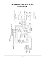
SERVICING INSTRUCTIONS
REPLACING PARTS
19
IMPORTANT
The work must be carried out by trained service engineers.
1. GENERAL
2. FAN MOTOR
IMPORTANT – The glass panel on this appliance should be
checked for any signs of damage on the front face of
the glass panel (scratches, scores, cracks or other
surface defects). If damage is observed, the glass
panel must be replaced and the appliance must not be
used until a replacement is installed. Under no
circumstances should the appliance be used if any
damage is observed. Please isolate the appliance
until a replacement glass panel has been obtained
and installed. Replacement glass panels can be
purchased from AGA Rangemaster via the dealer from
which the appliance was purchased or any other
AGA Rangemaster distributor.
1.1
All major components can be replaced from the front of
the cooker.
1.2
Make sure the mains electrical supply is isolated before
carrying out any servicing work.
BEFORE PROCEEDING TO CHANGE OR SERVICE
ANY ELECTRICAL ITEMS ISOLATE THE MAINS
ELECTRIC.
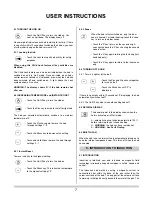
2.3
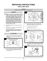
• Remove the top two screws 'A', retaining the fan
assembly panel and loosen the bottom two screws 'B'
2.4
• Lift the fan assembly panel up and off
• Lower onto the floor of the oven
• Remove all wires, but keep the Yellow Link wire, see
Diagram 3
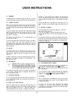
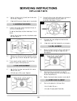
2.5
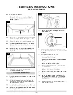
• Remove the central nut (left-hand thread) and separate
the impeller from the fan motor, See Diagram 4 Arrow A
AR1587
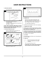
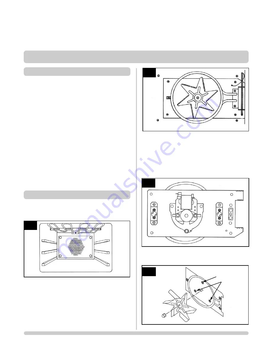
2.1
• Open the Fan Oven door and loosen the four screws
holding the fan cover. Lift the fan cover off the screws.
See Diagram 1.
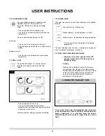
2.2
• Remove the thermostat phial, lifting it vertically from its
brackets. Take care not to damage the fine capillary
tube. See diagram 2, C
1
2
3
4
AR1587
AR1557
AR1592
AR1594
B
B

