background image

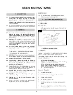
USER INSTRUCTIONS

contents are, in fact, heated by the pan. The pan rapidly reaches
the chosen temperature and quickly stops any cooking when
lifted away from the hob surface. It is this flexibility, speed and
control that many cooks find attractive.

Note:

You can only use pans that have a magnetic core. The
following are suitable for use with induction :

• Stainless steel
• Cast Iron
• Enamel on steel pans with non-stick interior

NOT Aluminium

To test whether your pan is suited to Induction, hold a fridge
magnet to the base of the pan; if the magnet sticks, it is
suitable for use on the Induction hob. Most modern pans are
marked to indicate whether they are suitable for induction
before purchasing.

5.2 ADVANTAGES

The speed of Induction compared to Gas or Radiant is
impressive. The example below shows on a 10 minute timescale
just how far ahead Induction really is:

Data compiled by E.G.O.

1.  Energy Consumption is minimised. Only contact with a 

suitable pan activates the magnetic current; a hugely efficient
way to use electric resources. The hob stops producing any
current when the pan is lifted and until it is returned.

2.  Cool down of contents of a pan takes a fraction of the time f

or Radiant, Gas and other fuels.

3.  The response to temperature control is swift and precise.

4.  Only the area beneath the saucepan is heated - the rest of 

the hob surface stays cool.

5.  The Induction Burner automatically adjusts its power 

depending on the size of the pan. The smaller the pan the 
less energy used.

6.  Soap and water are all it takes to clean.

6. USING THE INDUCTION HOB

2 LITRES OF WATER (FROM 20oC TO 90oC)

Induction

4.6 minutes

Gas

8.46 minutes

Radiant

9.00 minutes

Cast Iron

9.50 minutes

8

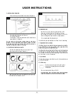
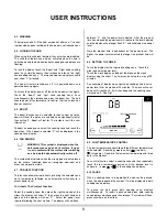
6.1 TURNING ON THE HOB

Touch the On/Off Key.  
The clock timer will show CL (Clock) and the display 

for the two cooking zones will illuminate with a

dot flashing beside each of them to show that they are awaiting
a selection.

Each time a touch control has been activated the hob will give a
beep to confirm.

If a selection is not made within 20 seconds the hob will
automatically power off.  The unit will beep when powering
down.  See Fig. 6

6.2 CONTROLLING A COOKING ZONE

Turn on the hob by touching 
Touch the display of the cooking zone. 

Then touch the slider, for a high setting touch the right hand end
of the slider for a low setting touch the left hand end.  With your
finger remaining in contract with he slider the set pint can be
increased /decreased by sliding your finger in the appropriate
direction.

6

Summary of Contents for Two-Oven

Page 1: ...or infirm This appliance is guaranteed for 3 years Parts 1 year Labour subject to the conditions on page 3 of this Instruction manual These Instructions must be left with the appliance for future reference and for consultation when servicing the appliance Please make the customer aware of the correct operation of the appliance before leaving these instructions with them The commissioning sheet fou...

Page 2: ...ation 10 Fault Finding 11 INSTALLATION INSTRUCTIONS TECHNICAL INFORMATION 12 SITE REQUIREMENTS 13 Appliance Location 13 Ventilation 13 INSTALLATION 14 Standards 14 Health and Safety 14 Electrical Tests 14 Location 15 Electrical Connection 15 Final Assembly 16 COMMISSIONING 17 WIRING DIAGRAM 18 CONTENTS 2 SERVICING INSTRUCTIONS 19 REPLACING PARTS 19 General 19 Fan Motor 19 Overheat Switches 20 Fan ...

Page 3: ...the above Appliance Commissioning Checklist is not fully completed by the installer and available for inspection by a Rayburn engineer IMPORTANT NOTICE Explain the operation of the appliance to the end user hand the completed instructions to them for safe keeping as the information will be required when making any guaranteed claims ELECTRICAL CHECK PASS FAIL 1 Polarity Checks 2 Earth bond continui...

Page 4: ...d your own safety 2 7 A cooker that is incorrectly installed altered in any way or not serviced can invalidate approval of the appliance its warranty and may affect your statutory rights 2 8 DO NOT place combustible materials onto the hotplate surfaces even when the cooker is off 2 9 DO NOT spray aerosols in the vicinity of this appliance while it is operating 2 10 Dragging pans or utensils across...

Page 5: ... used either as a grill a fan assisted oven or a fan assisted grill 3 9 GRILL only Turn the selector to point to the grill symbol Turn the grill thermostat dial to the desired temperature The neon indicates that the grill is ON PLEASE NOTE THAT THE GRILLING FUNCTION MUST ONLY BE CARRIED OUT WITH THE DOOR OPEN 3 4 REPLACING SHELVES Place shelf onto the stainless steel runner Diagram 2 Push the shel...

Page 6: ...Lower Oven can be run as a conventional oven with optional features Top element only for browning Bottom element for cooking bases i e flans Both elements for traditional roasting and baking Turn the Lower Oven thermostat to the desired temperature The neon indicates when the oven is heating up and goes out when the desired temperature is reached 3 13 BOTH FAN OVEN AND LOWER OVEN Remember to turn ...

Page 7: ...ase of the pan rather than the ceramic surface of the hob The only part of the ceramic surface to warm up is that part directly beneath the metal of the pan The USER INSTRUCTIONS 7 4 1 TURNING THE HOB ON Touch the On Off key to turn the Hob on You hear a short beep The display shows 0 A decimal point indicates each hob is waiting for activity If there is no activity within 10 seconds of switching ...

Page 8: ... of a pan takes a fraction of the time f or Radiant Gas and other fuels 3 The response to temperature control is swift and precise 4 Only the area beneath the saucepan is heated the rest of the hob surface stays cool 5 The Induction Burner automatically adjusts its power depending on the size of the pan The smaller the pan the less energy used 6 Soap and water are all it takes to clean 6 USING THE...

Page 9: ...ected to reduce heat up times boost will heat the pot over a cooking zone significantly faster than setting 9 Boost will last for 10 minutes or until the user intervenes To boost a cooking zone select the cooking zone and touch the boost key When boost is selected P will be displayed in the cooking zone display 6 6 PAN SENSOR WARNING This symbol is displayed when the hob cannot sense a pan on its ...

Page 10: ...d Radiant Hob The smooth surface of the zones for each hob type are easy to keep clean Ensure the ceramic surface is cool or cold before cleaning Clean the ceramic glass after each use to prevent any light spillage becoming embedded Light cooking spatters can be removed with a damp cloth and washing up liquid Rub dry with a clean cloth Heavy spatters on the Radiant hob including scale and water ma...

Page 11: ...work carried out on this cooker by any third party are not accepted by AGA Rangemaster Every enamelled part on your cooker is unique and has its own individual characteristics Coloured parts may differ slightly in shading This does not impair performance in any way and is quite normal 13 6 IMPORTANT CUSTOMER NOTICE Cosmetic damage stains and scratches produced by cooking and cleaning are NOT cover...

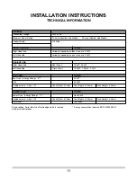
Page 12: ...7kW RADIANT HOB Right Hand Hob Dual Circuit 1 5kW 2 4kW Left Hand Hob Triple Circuit 1 05kW 1 95kW 2 7kW FAN OVEN POWER Fan Oven Energy Rating B 2 5kW Grill 2 55kW Usable volume Litres 37 Oven Width 355mm Oven Depth 460mm Oven Height 240mm LOWER OVEN POWER Lower Oven Energy Rating C Up to 2kW Usable volume Litres 37 Oven Width 355mm Oven Depth 460mm Oven Height 240mm Warmfront 160 Watts Rated volt...

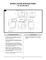
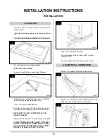
Page 13: ...g out or splitting 1 3 Adequate clearance must be provided in front of the appliance to allow it s complete removal from the location Certain serviceable components can only be changed by removing the cooker from it s location and gaining access to the rear of the appliance 1 4 The electric connection is channelled along the bottom left of the cooker see above Diagram 1 2 1 No purpose provided ven...

Page 14: ...vely tested and examined before despatch 2 2 This appliance is heavy and care must be taken when installing Use suitable equipment to prevent injury ELECTRICAL WARNING INSTALLATION OF THIS COOKER IS TO BE CARRIED OUT BY A QUALIFIED ELECTRICIAN TRAINED IN THE USE OF SPECIALIST EQUIPMENT WIRING EXTERNAL TO THE APPLIANCE MUST BE IN ACCORDANCE WITH THE CURRENT IEE WIRING REGULATIONS 17th Edition 3 1 T...

Page 15: ...ooker EQUALS the same height as kitchen surfaces if any MAKE SURE YOU HAVE ASSISTANCE AS THE COOKER IS HEAVY Manoeuvre the cooker on its pallet in front of the plinth IF THE KITCHEN UNITS ARE CLOSE TO THE LEFT SIDE OF THE COOKER YOU MAY NEED TO MAKE THE ELECTRICAL CONNECTION TO THE COOKER BEFORE IT SLIDES BACK INTO POSITION Slide off the pallet onto the plinth Check the cooker surface is level wit...

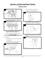
Page 16: ... in until it touches the cooker front and lock the nut in position Diagram 8 Fit the two towel rail cast iron ends to the rail Lock with the hex grub screw Diagram 9 Fit the towel rail assembly onto the threaded bar ensuring the gasket is fitted as in the following Diagram 10 Lock the towel rail assembly by fitting a washer and nut Diagram 11 16 INSTALLATION INSTRUCTIONS INSTALLATION 6 9 10 11 7 8...

Page 17: ...ULATION RESISTANCE CHECK IMPORTANT IF THERE IS NO MAINS SUPPLY OR THE ABOVE TESTS CANNOT BE CARRIED OUT ENSURE THAT A WARNING LABEL IS ATTACHED TO THE APPLIANCE STATING THAT IT SHOULD NOT BE USED UNTIL ELECTRICALLY TESTED BY A SUITABLY QUALIFIED ELECTRICIAN AND INFORM THE CUSTOMER Finally Complete the Appliance Commissioning Checklist on page 3 of this User and Installation guide ...

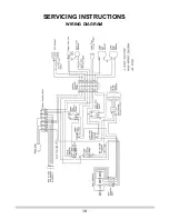
Page 18: ...SERVICING INSTRUCTIONS WIRING DIAGRAM 18 ...

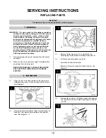
Page 19: ...GA Rangemaster distributor 1 1 All major components can be replaced from the front of the cooker 1 2 Make sure the mains electrical supply is isolated before carrying out any servicing work BEFORE PROCEEDING TO CHANGE OR SERVICE ANY ELECTRICAL ITEMS ISOLATE THE MAINS ELECTRIC 2 3 Remove the top two screws A retaining the fan assembly panel and loosen the bottom two screws B 2 4 Lift the fan assemb...

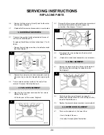
Page 20: ...holding the fan cover Lift the fan cover of the screws Diagram 6 4 2 Remove the three screws retaining the oven element and carefully pull forward the element to expose the connections See diagram 7 Arrow C 4 3 Disconnect the wires making sure they do not fall behind the oven 4 4 Replace the element and reassemble in reverse order 5 1 Remove the single screw from the rear of the element and the tw...

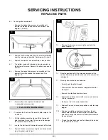
Page 21: ...n 7 3 Locate the fault control thermostat and pull off the knob 7 4 Remove the four screws securing the control panel and lower the panel onto its front 7 5 Remove the two screws securing the control to the panel Diagram 12 7 6 Note the positions of all the wires and disconnect the control Alternatively transfer each wire to the new control individually 7 7 Working from inside the controls area Ca...

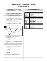
Page 22: ...rmostat and phial by following paragraphs 7 2 to 7 12 8 5 Reassemble the Lower Oven element and phial by reversing the order 8 6 Reassemble the Fan Oven assembly by reversing the order In the unlikely event that a problem occurs with any of the following features Induction Hob Radiant Hob Neon Indicators Warm Front The parts are serviceable only by an authorised Rayburn Service engineer contact yo...

Page 23: ... Stamp Registration Number 9TH SERVICE Date of Service Next Service Due Signed Dealer s Stamp Registration Number 2ND SERVICE Date of Service Next Service Due Signed Dealer s Stamp Registration Number 4TH SERVICE Date of Service Next Service Due Signed Dealer s Stamp Registration Number 6TH SERVICE Date of Service Next Service Due Signed Dealer s Stamp Registration Number 8TH SERVICE Date of Servi...

Page 24: ...y AGA Rangemaster Station Road Ketley Telford Shropshire England TF1 5AQ England Scotland Wales Tel 0845 6010398 Northern Ireland Tel 02891 270233 www agaliving com www agacookshop co uk www rayburn web co uk N00532AXX ...

Reviews: