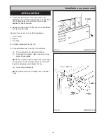


1.
Check that the hearth is level, then remove the
appliance from its transit wooden pallet, and position it
with its back against the wall and in its intended
position for flue connection.
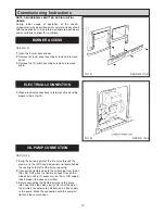
2.
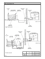
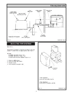
Connect and terminate the flue system in accordance
with these instructions.
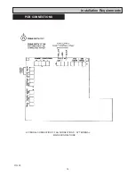
Connect the relevant services to the appliance:-
1. Oil (XT KPF)
2. Electric
3. Flue Pipe
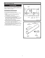
4.
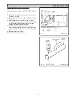
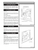
Fit plinth assembly (See Fig. 14).
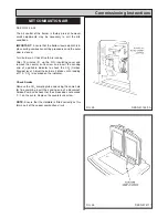
5.
Fit handrail assembly (See Fig. 15) as follows:
(i)
Fit mounting brackets to top plate loose.
(ii)
Fit handrail to brackets. Tigten up screw fixing
brackets to top plate.
NOTE:
The handrail ends are tapered to match taper
on top plate. The handrail should only be fitted with
tapered ends going inward toward the top.
(iii) Fit covers onto brackets
NOTE:
Tighten grub screw through hole in top door
hinge.
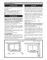
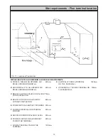
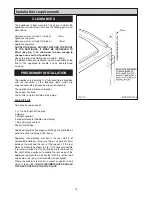
Installation requirements
16
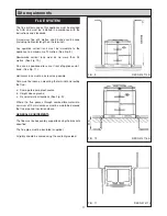
SITE LOCATION
FIG. 15
FIG. 14
DESN 514117 B
DESN 514191 A
Summary of Contents for XT- Oil
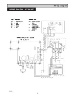
Page 24: ...24 Wiring Diagram FIG 27 WIRING DIAGRAM APPLIANCE...
Page 26: ...26...
Page 27: ...27...


