background image

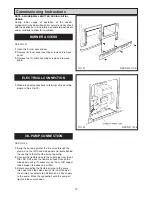
The Rayburn is a floor standing  cooker, fired by a
pressure jet oil burner. 

IMPORTANT

l

This appliance must only be used with Kerosene 
Class C2 Complying with BS2869 Part 2

l

A Fire Valve MUST be fitted in the oil supply line.

l

The supplied in line filter MUST be fitted.

THIS APPLIANCE IS A CONTROLLED SERVICE BY
DEFINITION AND REQUIRES EITHER FITMENT
UNDER THE REMIT OF BUILDING CONTROL OR
INSTALLATION BY AN OFTEC REGISTERED 105
TECHNICIAN (CLASSED AS A COMPETENT PERSON)
WHO CAN SELF CERTIFY HIS OWN WORKS.

This appliance must be commissioned by a competent
engineer such as an OFTEC approved.

The installation of the appliance must be in accordance
with the relevant requirements of the current Building
Regulations BS7671 (formerly IEE Wiring Regulations). It
should also be in accordance with the relevant British
Standard Codes of Practice.

BS 5410

Installation of oil fired appliances for space

heating and hot water purposes Part 1 Boilers of rate
output not exceeding 45kW.

The control of Pollution (Oil) Regulations.
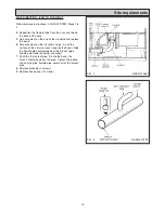
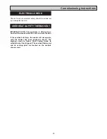
FLUE SAFETY DEVICE

For safety purposes a flue safety device is fitted. This will
only operate in adverse or blocked flue conditions. If the
switch has operated, it should be pushed in, to reset. If
this problem persists it is necessary to determine and
rectify the cause. If it is found necessary to reset more
than once this may indicate a flue blockage.
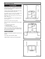
Appliance Hearth. 

The surface temperature of the floor

below the appliance does not exceed 100°C. The
constructional hearth described in current Building
Regulations does not apply. However this appliance must
be installed on a solid floor or base of incombustible
material which is capable of supporting the total weight.

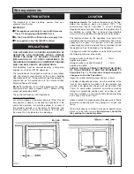
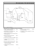
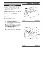
The location chosen for the appliance must permit the
installation and the provision of a satisfactory flue and an
adequate air supply. The location must also provide
adequate space for servicing and for air circulation around
the appliance. See “Installation of the Appliance”.

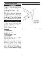
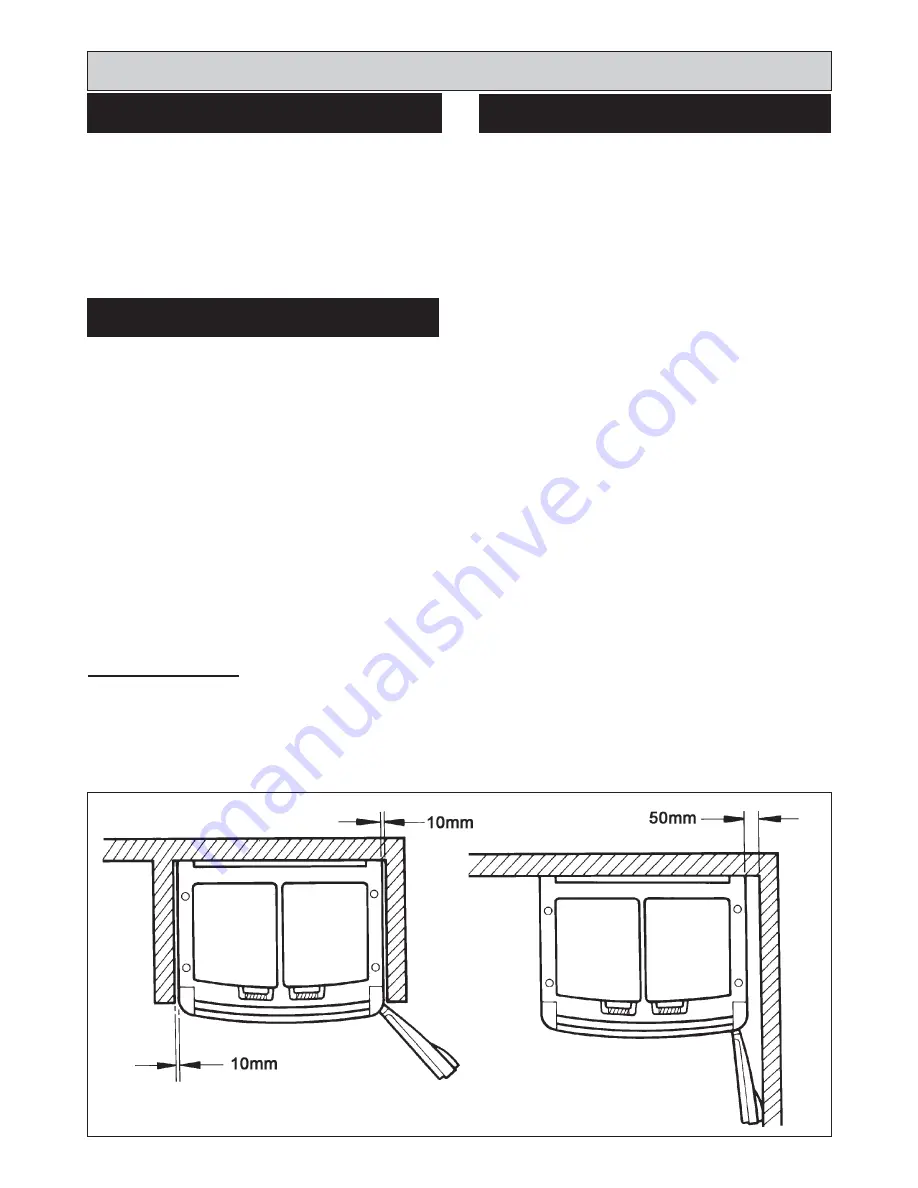
The space in which the appliance is to be fitted must have
the following minimum dimensions.

Between wall or unit and LH side of  

- 10mm

appliance top plate
Between wall or unit and RH side of

-  10mm

appliance top plate

SHOULD THE WALL PROJECT BEYOND THE FRONT
OF THE APPLIANCE, IT MUST BE INCREASED TO
50mm (See Fig. 1). To allow door to open enough to
change oven and shelf positions.

Above the raised insulating cover handle -  60mm

In addition, adequate clearance must be available at the
front of the appliance to enable it to be operated and
serviced. Flue pipes and fittings must not be closer than
10mm to combustible materials and where passing
through a combustible partition such as ceiling or roof,
must be enclosed in a non-combustible sleeve providing
an air space of at least 10mm.

Spaces around flue pipes passing through walls or floors
should be sealed against the passage of smoke and
flame.

Where the cooker is to stand in a recess or against a wall
which is to be tiled, 

in no circumstances should the

tiles overlap the cooker top plate.
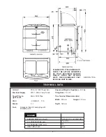
Site requirements

5

REGULATIONS

LOCATION

INTRODUCTION

FIG. 1

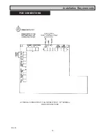
Summary of Contents for XT- Oil

Page 1: ...T Oil K P F 10 13 EINS 514137 raywarranty aga web co uk DESN 514112 B Remember when replacing a part on this appliance use only spare parts that you can be assured conform the safety and performance s...

Page 2: ...S 15 REQUIREMENTS PRELIMINARY INSTALLATION 15 SITE LOCATION 16 INSTALLATION 17 PCB CONNECTIONS 18 COMMISSIONING BURNER ACCESS 19 INSTRUCTIONS ELECTRICAL CONNECTION 19 OIL PUMP CONNECTION 19 ELECTRICAL...

Page 3: ...armful if inhaled May be irritating to skin eyes nose and throat When handling avoid contact with skin or eyes Use disposable gloves face masks and eye protection After handling wash hands and other e...

Page 4: ...Appliance 350 Kg Firing Rate 1 44 l h Flue Terminal Dimensions mm Width 500 mm Height 210 mm Depth 180 mm TECHNICAL DATA DESN 514170 B BURNER NOZZLE US g h 0 40 80 H LE DANFOSS 7 6 110 24 14 6 OIL PRE...

Page 5: ...appliance does not exceed 100 C The constructional hearth described in current Building Regulations does not apply However this appliance must be installed on a solid floor or base of incombustible m...

Page 6: ...ump for ease of burner removal The minimum recommended oil tank size is 1400 litres Mild Steel Tanks should be to BS 799 Part 5 and plastic tanks to OFTEC standard OFS T100 HOWEVER in the interests of...

Page 7: ...Site requirements 7 DESN 514167 C DESN 514169 B FIG 2 MAXIMUM LENGTH METRES H METRES 10mm OD 0 100 3 0 100 3 5 88 4 0 40 Single Pipe oil system Two Pipe oil system...

Page 8: ...em To convert to a two pipe system See Fig 4 Sections BURNER ACCESS steps 1 to 3 BURNER REMOVAL steps 1 to 5 PUMP FILTER REPLACEMENT steps 1 2 1 Remove middle screw 2 Remove horseshoe washer 3 Replace...

Page 9: ...per factory set remove bend from manifold and pipe A Smear sealant on the end of the manifold and replace bend onto the manifold ensuring it is fully on and sweeps under the burner chamber 5 Smear the...

Page 10: ...n the first end of pipe A and the surface of the 28mm branch towards the bend Slide the flexible pipe completely over the branch pipe should point towards burner chamber 7 Push the first end of pipe A...

Page 11: ...ce via 1 bend See Fig 11 Horizontal runs must be as level as possible Care must be taken on mounting the terminal and routing the flue a Damage to damp proof course b Height above ground c General ter...

Page 12: ...TECTION D BELOW A GUTTER OR A BALCONY 600mm WITHOUT PROTECTION E FROM VERTICAL SANITARY PIPEWORK 300mm F FROM AN INTERNAL OR EXTERNAL 300mm CORNER G ABOVE GROUND OR BALCONY LEVEL 300mm H FROM A SURFAC...

Page 13: ...rtical plane to reduce the risk of blockage Ducts should be sized so as to reduce resistance to air flow 4 The ventilation requirement for kitchens in Part F of the Building Regulations is for mechani...

Page 14: ...connection to the mains should be readily accessible and adjacent to the appliance The installation should be protected by a 30mA Residual Current Circuit Breaker RCCB The minimum requirement for the...

Page 15: ...oil filter and the flexible oil feed pipe FLUE PIPE KIT Flue pipe kit comprises of 3 x 1 metre length of flue pipe 3 elbows 3 straight couplers 6 support brackets saddle and clamps 1 tube ultra grey...

Page 16: ...lectric 3 Flue Pipe 4 Fit plinth assembly See Fig 14 5 Fit handrail assembly See Fig 15 as follows i Fit mounting brackets to top plate loose ii Fit handrail to brackets Tigten up screw fixing bracket...

Page 17: ...ay require to be shortened or lengthened depending on wall thickness See Fig 18 7 Using the large wall fixings permanently fix back plate to the wall remove outer cover first 8 Wire the fan to the sup...

Page 18: ...18 Installation Requirements FIG 20 EXTERNAL CONNECTIONS FAN CONNECTIONS AT TERMINAL MAINS CONNECTIONS PCB CONNECTIONS...

Page 19: ...nsing phial of the fire valve through the grommet in the left hand side panel and locate behind the casting to the left of the burner opening 2 Connect the flexible hose to the outlet pipe from the oi...

Page 20: ...manual reset button If the overheat stat trips the cooker will not operate until the button has been pushed in reset The engineer needs to follow Fault Finding Guide to establish why it has tripped Th...

Page 21: ...f the signal light in the reset button of the control box see Fig 24 In this event wait at least one minute then press the re set button to restart SEE FIG 23 Whilst the burner is running vent air fro...

Page 22: ...ew and insert the sensing end of a portable indicator to check the CO2 Carbon Dioxide level Adjust the burner air intake until a reading of 11 0 CO2 is recorded on the indicator Check Smoke Remove the...

Page 23: ...l then be illuminated WAIT 1 MINUTE BEFORE RESETTING THE CONTROL BOX 1 Advise the User that for continued efficient and safe operation of the appliance it is important that adequate servicing is carri...

Page 24: ...24 Wiring Diagram FIG 27 WIRING DIAGRAM APPLIANCE...

Page 25: ...NG ALL WIRING TO THE IEE REGULATION BY A QUALIFIED ENGINEER USERS INSTRUCTIONS GUIDE PROGRAMMER AND TIMER COMBINATION 1 The Time of Day alarm and Minute Minder functions can all be used without effect...

Page 26: ...26...

Page 27: ...27...

Page 28: ...er s policy of continuous product improvement the Company reserves the right to change specifications and make modifications to the appliance described at any time Manufactured by AGA Rangemaster Stat...

Reviews: