background image

The Rayburn is a floor standing  cooker, fired by a gas
burner.

The burner fitted to this appliance has been designed
and constructed exclusively for use with the Rayburn
XT Cooker and MUST not be used on any other
appliances or any other uses.

In the interests of safety all gas appliances should be
installed by competent persons in accordance with the
regulations in force.

Installation Pipes

Pipework from the meter to the appliance must be of
adequate size. It is recommended that a minimum of ø22
mm copper tubing is used to within 1m of the appliance.
A reduction to ø15mm is permissible over the last metre
of the appliance. Do not use pipes of a smaller size than
the appliance gas connection. To avoid undue stress on
pipework and burner, adequate support should be used
when connecting and disconnecting union. The complete
installation must be tested for soundness and purged in
accordance with the regulations in force.

FLUE SAFETY DEVICE

For safety purposes a flue safety device is fitted. This will
only operate in adverse or blocked flue conditions. If the
switch has operated, it should be pushed in, to reset. If
this problem persists it is necessary to determine and
rectify the cause. If it is found necessary to reset more
than once this may indicate a flue blockage.

The appliance is floor mounted and must be installed on
a solid floor or base of non-combustible material which is
capable of supporting the total weight.

The location chosen for the appliance must permit the
installation and the provision of a satisfactory flue and an
adequate air supply. The location must also provide
adequate space for servicing and for air circulation around
the appliance. See “Installation of the Appliance”.

The space in which the appliance is to be fitted must have
the following minimum dimensions.

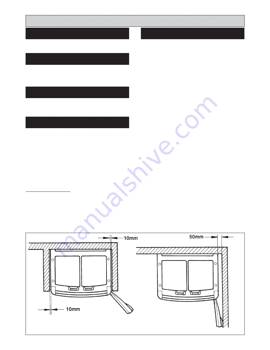
Between wall or unit and LH side of appliance -  10mm
top plate

Between wall or unit and RH side of appliance -  10mm
top plate

SHOULD THE WALL PROJECT BEYOND THE FRONT
OF THE APPLIANCE, THEN THE GAP AT THE R.H.
SIDE MUST BE INCREASED TO 50mm. TO ALLOW
DOOR TO OPEN ENOUGH TO CHANGE OVEN AND
SHELF POSITIONS, (SEE FIG. 1).

Above the raised insulating cover handle -  60mm

In addition, adequate clearance must be available at the
front of the appliance to enable it to be operated and
serviced. Flue pipes and fittings must not be closer than
10mm to combustible materials and where passing
through a combustible partition such as ceiling or roof,
must be enclosed in a non-combustible sleeve providing
an air space of at least 10mm.

Spaces around flue pipes passing through walls or floors
should be sealed against the passage of smoke and
flame.

Where the cooker is to stand in a recess or against a wall
which is to be tiled, in no circumstances should the tiles
overlap the cooker top plate.

Site requirements

5

IMPORTANT

LOCATION

INTRODUCTION

REGULATIONS

GAS SUPPLY

FIG. 1

DESN 514109

Summary of Contents for XT

Page 1: ...T Gas GPF 10 13 EINS 514103 raywarranty aga web co uk DESN 514112 B Remember when replacing a part on this appliance use only spare parts that you can be assured conform to the safety and performance specification that we require Do not use reconditioned or copy parts that have not been clearly authorised by AGA ...

Page 2: ...TE LOCATION 14 SETTING COMBUSTION 15 INSTALLATION INSTRUCTIONS BURNER ACCESS 16 ELECTRICAL CONNECTION 16 BOILER CONTROL BURNERTECH BURNER 17 ELECTRICAL CHECK BURNERTECH BURNER 17 COMBUSTION DISCHARGE DEVICE BURNERTECH 17 BURNER OVERHEAT SAFETY THERMOSTAT 17 BURNER CONTROL ECOFLAM BURNER 18 ELECTRICAL CHECK ECOFLAM BURNER 18 COMBUSTION DISCHARGE DEVICE ECOFLAM 18 BURNER ANCILLARY CONTROLS CHECK 19 ...

Page 3: ...orn when handling where applicable the pertinent parts that contain any of the listed materials that could be interpreted as being injurious to health and safety see below for information Firebricks Fuel beds Artificial Fuels When handling use disposable gloves Fire cement When handling use disposable gloves Glues and Sealants Exercise caution if these are still in liquid form use face mask and di...

Page 4: ...uel Propane G31 I3P Gas Inlet R 1 2 1 2 BSP TAPER Electrical Supply 230V 50Hz 3 amp Fused Flue Pipe Diameter 54mm St St Flue Terminal Size Width 500mm Height 210mm Depth 180mm Burner Inlet Pressure 37mbar CO 0 50 ppm CO2 9 4 10 8 Heat Input 14 6 kW Unpacked Appliance Weight 350 Kg 4 TECHNICAL DATA DESN 514106 B PLEASE NOTE IT IS ADVISABLE TO CHECK THE ACTUAL SIZE WIDTH OF YOUR APPLIANCE BEFORE FIN...

Page 5: ...a solid floor or base of non combustible material which is capable of supporting the total weight The location chosen for the appliance must permit the installation and the provision of a satisfactory flue and an adequate air supply The location must also provide adequate space for servicing and for air circulation around the appliance See Installation of the Appliance The space in which the appli...

Page 6: ...e appliance The point of connection to the mains should be readily accessible and adjacent to the appliance The installation should be protected by a 30mA Residual Current Circuit Breaker RCCB The minimum requirement for the power cable is that it should be a 3 core PVC sheathed flexible cord 85ÞC min at least 0 75mm2 24 x 0 2mm to the relevant standard WARNING THIS APPLIANCE MUST BE EARTHED In th...

Page 7: ...e is to be routed as per factory set remove bend from manifold and pipe A Smear sealant on the end of the manifold and replace bend onto the manifold ensuring it is fully on and sweeps under the burner chamber 5 Smear sealant over the surface of the 28mm branch on pipe A Push the flexible pipe 30 40mm on to the branch and tighten the jubilee clip 6 Smear sealant on the first end of pipe A and fit ...

Page 8: ... bend 6 Smear sealant on the first end of pipe A and the surface of the 28mm branch towards the bend Slide the flexible pipe completely over the branch pipe should point towards burner chamber 7 Push the first end of pipe A onto the bend the branch should be above the pipe Tighten the jubilee clip ensuring the flexible pipe covers all of the branch pipe 8 Replace brackets 4 screws 9 Replace back p...

Page 9: ...bove ground c General terminal locations See Fig 9 Where the flue passes through combustible material a minimum of 10mm clearance must be maintained around the flue pipe and insulation sleeve General Requirements The flue pipe must be adequately supported using the brackets specified The flue pipe must be insulated supplied All joints should be sealed using the sealant provided The appliance can o...

Page 10: ...AL DRAIN PIPE OR SOIL 150mm PIPE H FROM AN INTERNAL OR EXTERNAL 200mm CORNER OR TO A BOUNDARY ALONGSIDE THE ENAMEL I ABOVE GROUND ROOF OR BALCONY 300mm LEVEL J FROM A SURFACE OR BOUNDARY 600mm FACING THE TERMINAL K FROM A TERMINAL FACING THE 1200mm TERMINAL L FROM AN OPENING IN THE CAR PORT 1200mm INTO THE BUILDING M VERTICALLY FROM A TERMINAL ON 1200mm SAME WALL N HORIZONTALLY FROM A TERMINAL ON ...

Page 11: ...lue termination pipe may required to be shortened or lengthened depending on wall thickness See Fig 12 7 Using the large wall fixings permanently fix back plate to the wall removing outer cover first 8 Wire the fan to the supply cable to the terminal block on the back plate See Fig 13 Using the 3 core cable provided run cable back to flue extractor circuit control at the bottom right hand side of ...

Page 12: ...12 Site Requirements PCB CONNECTIONS FIG 14 EXTERNAL CONNECTIONS FAN CONNECTIONS AT TERMINAL MAINS CONNECTIONS ...

Page 13: ...distance bracket The cooker handrail FLUE PIPE KIT Flue pipe comprises of 3 x 1 metre of flue pipe 3 elbows 3 straight couplers 6 support brackets saddle and clamps 1 tube ultra grey sealant Pack of fastenings Additional lengths of pipes and fittings are available as optional extras including a 45 angle bend Appliance rear distance bracket If the rear wall is of combustible material there must be ...

Page 14: ...Flue Pipe 3 Fit plinth assembly See Fig 16 4 Fit handrail assembly See Fig 17 as follows i Fit mounting brackets to top plate loose ii Fit handrail to brackets Tighten up screw fixing brackets to top plate NOTE The handrail ends are tapered to match taper on top plate The handrail should only be fitted with tapered ends going inward toward the top iii Fit covers onto brackets NOTE Tighten grub scr...

Page 15: ...ures Ensure the outer door is closed Turn the burner on After 15 minutes lift up the RH insulating cover and remove the countersunk screw and insert the sensing end of a portable indicator to check the CO2 Carbon Dioxide level CO 0 50 ppm CO2 8 2 9 9 Natural Gas CO2 10 3 10 7 Propane If these volumes cannot be obtained check the gas rate adjust throttle screw if required and allow reading to stabi...

Page 16: ...ner panel securing screws and remove panel 3 Remove the 3 plinth securing screws and remove plinth 1 Make electrical connections to terminal strip as wiring diagram See Fig 14 Installation Instructions FIG 18 DESN 514110 B BURNER ACCESS ELECTRICAL CONNECTION ...

Page 17: ...conditions If the switch has operated it should be pushed in to reset If this problem persists contact your local engineer to determine and rectify the cause It is important not to reset more than once as this may indicate a flue blockage WARNING The combustion discharge safety device must not be interfered with or rendered inoperative as this could interfere with the safe operation of the applian...

Page 18: ...he on position Check inlet gas pressure at test point Checks to ensure electrical safety should be carried out by a competent person For safety purposes a combustion discharge safety device is fitted This will only operation under adverse flue conditions If the switch has operated it should be pushed in to reset If this problem persists contact your local engineer to determine and rectify the caus...

Page 19: ...ontinued efficient and safe operation of the appliance it is important that adequate servicing is carried out at regular 12 monthly intervals 2 Hand the Operating Instructions to the User and demonstrate the correct operation of the appliance and system controls 3 Leave the Installation and Servicing Instructions with the User Installation Instructions ANCILLARY CONTROLS CHECK INSTRUCT THE USER 19...

Page 20: ...20 Wiring Diagram FIG 21 WIRING DIAGRAM APPLIANCE ...

Page 21: ...GULATION BY A QUALIFIED ENGINEER USERS INSTRUCTIONS FOR PROGRAMMER AND TIMER COMBINATION 1 The Time of Day alarm and Minute Minder functions can all be used without affecting the external programmer timings 2 When using Auto Cook Function on the internal timer ensure the external wall programmer is in the continuous ON mode 3 When using the external wall programmer ensure it is set correctly i e t...

Page 22: ...22 ...

Page 23: ...23 ...

Page 24: ...ter s policy of continuous product improvement the Company reserves the right to change specifications and make modifications to the appliance described at any time Manufactured by AGA Rangemaster Station Road Ketley Telford Shropshire TF1 5AQ England www rayburn web co uk www agacookshop co uk ...

Reviews: