Site requirements
The flue can be to the left or right of the appliance. The
cooker is supplied with the flue pipe to the left, this can be
adjusted to suit the installation.
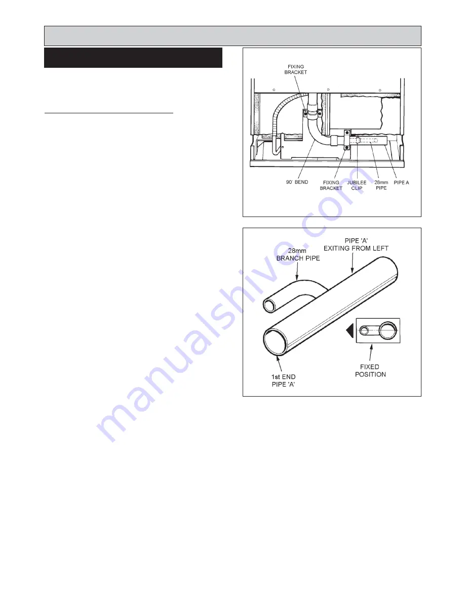
FLUE DIRECTION - EXIT TO THE LEFT
1.
Remove lower back panel (7 screws).
2.
Unscrew the two fixing brackets and remove. (See
Fig. 2).
3.
Slacken the jubilee clip, fixing flexible pipe to
horizontal pipe (A). (See Fig. 2).
4.
If the flue pipe is to be routed as per factory set,
remove bend from manifold and pipe A.
Smear sealant on the end of the manifold, and replace
bend onto the manifold, ensuring it is fully on and
sweeps under the burner chamber.
5.
Smear sealant over the surface of the 28mm branch
on pipe ‘A’. Push the flexible pipe 30-40mm on to the
branch and tighten the jubilee clip.
6.
Smear sealant on the first end of pipe ‘A’ and fit to
bend ensuring the branch pipe is slightly above
centre.
7.
Replace fixing brackets (4 screws).
8.
Replace back panel (7 screws) and position cooker.
FLUE SYSTEM
7
FIG. 2
DESN 512771
DESN 512770
FIG. 3
Summary of Contents for XT
Page 20: ...20 Wiring Diagram FIG 21 WIRING DIAGRAM APPLIANCE ...
Page 22: ...22 ...
Page 23: ...23 ...


