RCMDC-6627-PF-48
INSTALL INSTRUCTIONS
www.raycap.com
©Raycap • All rights reserved
320-1204 Rev.E
Page 20 of 38
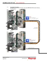
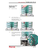
Note:
Selector switch set to
“•” or ”1” for Tower Top mode
Alarm
Outputs
to BTS
Note:
Selector switch set to
“3” for Base mode
address “1”
Note:
Selector switch set to
“2” for Base mode
address “0”
Daisy Chain
Output to next
Base unit
Daisy Chain Input
11.9
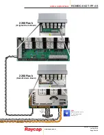
RCMDC-6627-PF-48 at the Tower Top connected to (2) RCMDC-2260-RM-48 with Retrofit Kits at the base.
This wiring scenario will be almost identical to (2) base-located RCMDC-3315-PF-48 units with Retrofit Kits.
Tower


