
5 INSTALLATION
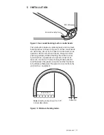
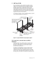
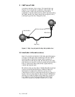
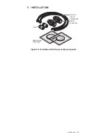
Allow extra cable to form several service loops along the
cable run, if possible. Band together the cable forming the
loops using stainless steel adjustable gear clamps or tie
wire. Keep the diameter of the loops as large as practically
possible. During future maintenance, replacement, or
relocation of equipment, the extra cable can be used to
service or rewire the equipment without having to replace
the cable.
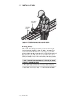
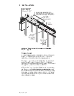
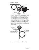
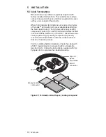
Once the cables have been pulled into position, secure the
cables to the rungs of the cable tray every 2 ft (610 mm)
using stainless steel bands, stainless steel tie wire, or
adjustable gear clamps. This ensures a neat installation,
prevents movement of the cables, and is particularly
important in the case of vertical runs of cable as it
prevents the top section of cable from supporting the
weight of the entire vertical cable run.
For further information on cable tray installations, contact
nVent Technical Support, see Section 1.1.
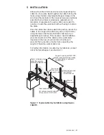
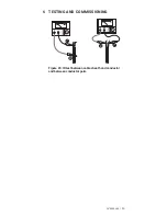
Steel channel
MI cable secured to rungs
of tray every 2 ft (610 mm)
Service loop
(one or more
loops of cable)
Steel rod securely
anchored to
structure above
Steel or stainless steel
cable tray securely
anchored to steel channel
Support spacing per NEC/CEC,
other national electrical codes
and standards, or customer
specification
Ground
conductor
Figure 11: Typical cable tray installation using trapeze
supports
nVent.com | 21
Summary of Contents for pyrotenax Alloy 825
Page 1: ...MI Cable Industrial Wiring Installation Manual For Alloy 825 Sheath Cables ...
Page 4: ...iv nVent com ...
Page 46: ...42 nVent com ...
Page 47: ...nVent com 43 ...